Voltage detecting apparatus

a voltage detection and apparatus technology, applied in secondary cells, batteries, instruments, etc., can solve the problems of leakage faults that tend to occur in paths to which high voltage is applied, the voltage range in which diagnostic voltage can be inputted is smaller than the actual use value, and the inability to detect leakage faults with high accuracy. , to achieve the effect of high accuracy detection

Active Publication Date: 2019-04-23
YAZAKI CORP
View PDF23 Cites 4 Cited by
  • Summary
  • Abstract
  • Description
  • Claims
  • Application Information

AI Technical Summary

Benefits of technology

[0013]According to the voltage detecting apparatus according to the invention, high-accuracy detection can be performed while expanding an input voltage range of the diagnostic voltage from a low voltage to a high voltage.
[0015]According to this voltage detecting apparatus, by making a determination by the capacitive voltage dividing ratio, the voltage dividing circuit configuration itself can freely be changed and also, diagnostic accuracy can be improved more remarkably than ever before in terms of detection of a leakage fault at the time of applying a high voltage.
[0017]According to this voltage detecting apparatus, by making a determination by the resistive voltage dividing ratio, the voltage dividing circuit configuration itself can freely be changed and also, the diagnostic accuracy can be improved more remarkably than ever before in terms of detection of the leakage fault at the time of applying the high voltage.
[0020]The invention can determine whether or not the circuit network is normal based on the relative reference by determining whether or not the circuit network including the measuring part is normal based on the voltage dividing ratio generated inside the self-diagnostic circuit, with the result that the voltage detecting apparatus capable of high-accuracy detection while expanding the input voltage range of the diagnostic voltage from the low voltage to the high voltage can be provided.

Problems solved by technology

However, in the technique described in Patent Reference 1, the voltage range in which the diagnostic voltage can be inputted is smaller than an actual use value and is limited.
Hence, there is a fear that a leakage fault tending to occur in a path to which a high voltage is applied cannot be detected with high accuracy.

Method used


Image

  • Voltage detecting apparatus
  • Voltage detecting apparatus
  • Voltage detecting apparatus

Examples


second embodiment

[0092]In a second embodiment, a power source voltage generating part 2, a charge pump circuit 3, power source paths 11, a cut off switch 13 and a circuit separation switch 15 have a function and a configuration similar to those of the first embodiment. Hence, description of the function and the configuration similar to those of the first embodiment is omitted in the second embodiment.

[0093]A self-diagnostic circuit 5 in the second embodiment is configured to differ from the self-diagnostic circuit 4 in the first embodiment. Hence, the self-diagnostic circuit 5 configured to differ from the self-diagnostic circuit 4 in the first embodiment will be described concretely.

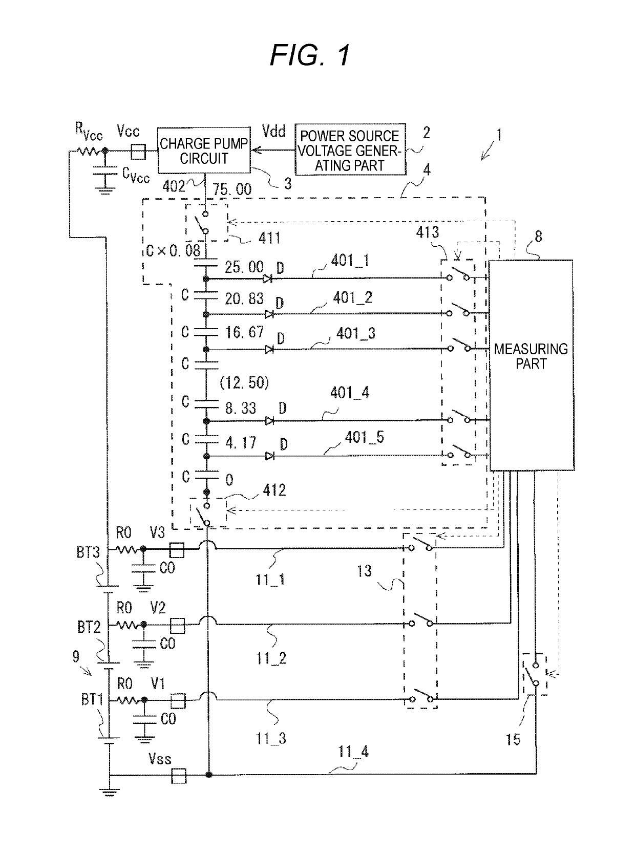
[0094]FIG. 4 is a diagram showing a circuit configuration example of a voltage detecting apparatus 1 according to the second embodiment. Electric power is supplied to the self-diagnostic circuit 5 by the charge pump circuit 3. The self-diagnostic circuit 5 includes plural circuit elements connected in series, and curren...


PUM

PropertyMeasurementUnit
diagnostic voltageaaaaaaaaaa

Abstract

A voltage detecting apparatus includes: an assembled battery made of plural cells, a self-diagnostic circuit, and a measuring part for measuring the plural cells or measuring a diagnostic voltage generated by the self-diagnostic circuit. Electric power is supplied to the self-diagnostic circuit by a charge pump circuit. The self-diagnostic circuit includes plural circuit elements connected in series, and a current path connected to the measuring part and formed in correspondence with each of the plural circuit elements, and the measuring part includes a multiplexer for switching a state of connection between each of the current paths and the circuit network. The measuring part determines whether or not the circuit network is normal based on a voltage dividing ratio by the circuit element corresponding to the current path switched by the multiplexer.

Description

CROSS REFERENCE TO RELATED APPLICATION[0001]This application is based on Japanese Patent Application (No. 2015-211434) filed on Oct. 28, 2015, the contents of which are incorporated herein by reference. Also, all the references cited herein are incorporated as a whole.BACKGROUND OF THE INVENTION[0002]1. Technical Field[0003]The present invention relates to a voltage detecting apparatus.[0004]2. Background Art[0005]Conventionally, a secondary battery mounted in a hybrid vehicle or an electric vehicle is a battery formed by connecting plural cells in series, and is used as a power supply source of a motor for driving. Since such a secondary battery may deteriorate due to secular use of each of the cells, a diagnostic device for diagnosing whether or not a charging voltage of each of the cells is normal is formed.[0006]Also, such a diagnostic device includes a device for detecting whether or not a circuit network configured in a path ranging from a detection path of a cell to an AD con...

Claims


Application Information

Patent Timeline
Patent Type & Authority Patents(United States)
IPC IPC(8): G01R31/36H01M10/48G01R31/396H01M10/42
CPCG01R31/396B60L58/13H01M10/4285H01M10/482H01M2220/20G01R31/3835G01R31/006Y02E60/10
Inventor IZAWA, TAKAAKI
Owner YAZAKI CORP
Why Eureka
Try Eureka