
Heavy equipment concrete core drill attachment

a technology of concrete core drill and attachment, which is applied in the direction of drilling tools, manufacturing tools, transportation and packaging, etc., can solve the problems of increasing movement, less support, and inevitable binding of the bit, and achieves the effect of avoiding the formation of a splint and a splin

Active Publication Date: 2019-05-07
THORNTON LEE C
View PDF7 Cites 2 Cited by
  • Summary
  • Abstract
  • Description
  • Claims
  • Application Information

AI Technical Summary

Benefits of technology

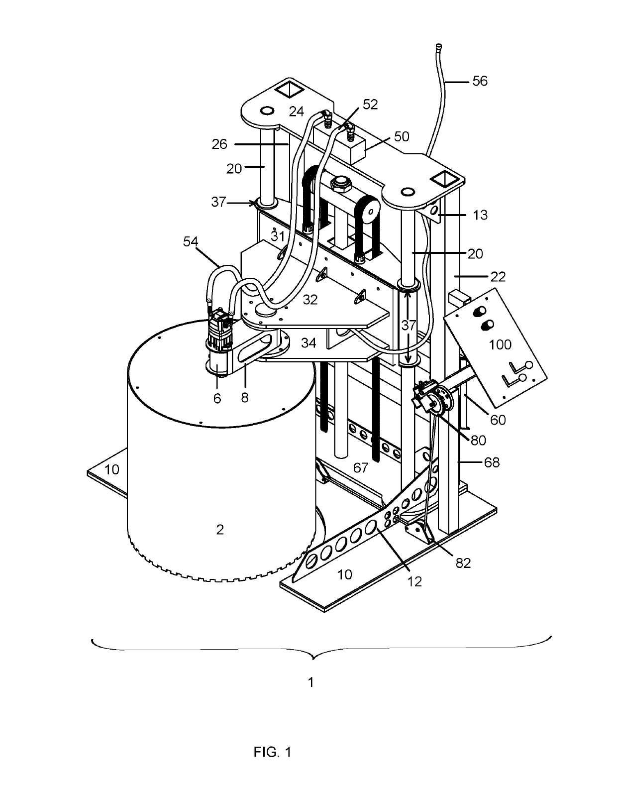
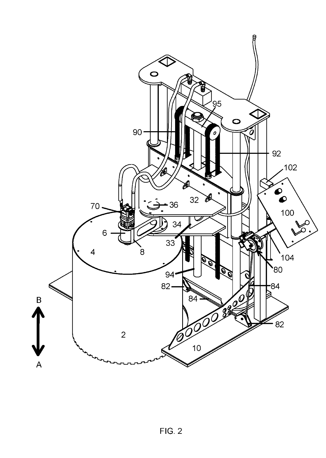
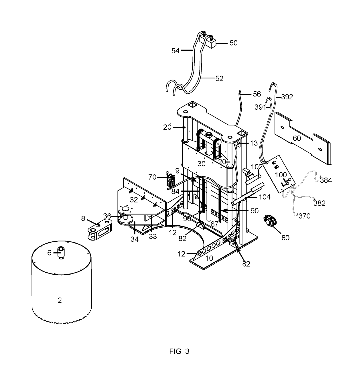
The invention is about an apparatus for drilling circular holes in concrete and asphalt for underground access or equipment installation. It can be attached to a skid steer or front loader and can also be used independently of a piece of heavy equipment. The apparatus is stable and efficient, and allows for quick setup and drilling of holes in slabs of concrete or asphalt. Previous devices required multiple users and were less stable, making the coring process slow and difficult. The invention solves these issues and meets the need for a more stable and cost-effective apparatus for drilling holes in concrete and asphalt.

Problems solved by technology

The limited contact of the rollers or bushings crates a situation where there is insufficient support on that side allowing for significant movement of the support structure.
This movement creates excessive wear on the rollers or bushings causing more movement, less support, and inevitable binding of the bit.
The single-mast system of Faircloth creates an extreme cantilever situation.
As with any lever, as the length of the arm increases, the downward force also increases and the instability becomes more severe causing more wear and more binding.
The mast and rollers or bushings are simply not designed to handle that amount of stress.
When the friction becomes too great, the bit binds and can become stuck in the substrate causing increased wear on the machine, increased wear on the bit, increased time coring holes, and a potential safety hazard.
In order to stabilize the Faircloth saw for cutting, the machine requires significant time to position correctly because the device requires that both the front loader and the saw be positioned separately in a two-step process (Col. 2, 25-31); it is difficult to position both the front loader and the saw in the correct position to cut a hole in the desired location; the device may become unstable during operation unless the position of the drum saw is level with the position of the pair of supports 108 thus the device cannot be used in an area unless the full length of the device is level reducing the applications the device may be utilized; and the means to move the saw up and down to drill a hole is positioned several feet from the hydraulic controls which requires two people positioned at opposite ends of the device to operate the device.

Method used


Image

  • Heavy equipment concrete core drill attachment
  • Heavy equipment concrete core drill attachment
  • Heavy equipment concrete core drill attachment

Examples


embodiment 300

[0096]The triangular brace system of the three-post embodiment 300 transfers vibration and kickback from the drum saw and distributes it to both the front and rear frame assembly. Because of this distribution of vibration and kickback, there is less wear on the drum saw extending the life of the drum saw. Additionally, the reduction in vibration and kickback reduces the frequency of the bit binding allowing the drum saw to cut more efficiently and produces cleaner cuts. The three-post embodiment is heavier and adds additional support for the carriage resulting in more stability than the two-post embodiment.

[0097]The pulley system includes winch 80, a number of pulleys 82, cable 84, and cable junction plate 182. The pulley systems allows a user to crank on winch 80 to spool cable 84, causing the cable to tighten through pulleys 82, driving drum saw bit 2 in a downward direction to core a hole. Note that pulleys 82 and cable 84 are secured and strung in multiple locations along base 3...

embodiment 401

[0116]FIG. 45 shows skid steer 200 (with water tank 140 attached to its roof) ready to attach the four-post embodiment 401. FIG. 46 shows a top view of the device. Rectangular bracket 425 includes interior cavities 23 and 27 that represent the interior of hollow frame support column 22 and frame support column 26, respectively. Drum saw bit 2 is positioned beneath motor mount top and bottom plates 432 and 434 (434 is shown in FIG. 43). Motor 70 powers drum saw bit 2 as it cores a hole. Motor 70 is supplied by hydraulic motor supply hose 52 and fluid is returned to the hydraulic system via hydraulic motor return hose 54 via hydraulic junction box 50. Pulleys 82 attached to the underside of rectangular bracket 425. Winch 80 with winch crank 81 are located proximate to control panel 100 so that a single user has ready access to all controls while operating the device.

[0117]FIG. 47 shows a side view of the device with four frame support columns. Winch 80 and control panel 100 are positi...


PUM

PropertyMeasurementUnit
depthsaaaaaaaaaa
diameteraaaaaaaaaa
timeaaaaaaaaaa

Abstract

The present invention is an attachment that reversibly connects to a skid steer, front loader, or other heavy equipment. The attachment allows a user to quickly and efficiently core holes in concrete and asphalt. The attachment comprises a frame assembly that rests upon the surface of concrete being cored and a carriage assembly. The carriage assembly connects a drum saw to the frame assembly. The carriage assembly moves vertically up and down along the length of the frame assembly while coring a hole in concrete. The attachment includes two, three, and four-post embodiments. The three and four-post embodiments provide include a larger frame assembly that provides additional stability to the attachment while allowing the user to quickly reposition the attachment to core additional holes.

Description

CROSS-REFERENCE TO RELATED APPLICATIONS[0001]This application does not claim the benefit of priority to any prior-filed application.STATEMENT REGARDING FEDERALLY SPONSORED RESEARCH OR DEVELOPMENT[0002]Not Applicable.THE NAMES OF THE PARTIES TO A JOINT RESEARCH AGREEMENT[0003]Not applicable.INCORPORATION-BY-REFERENCE OF MATERIAL SUBMITTED ON A COMPACT DISC OR AS A TEXT FILE VIA THE OFFICE ELECTRONIC FILING SYSTEM[0004]Not applicable.STATEMENT REGARDING PRIOR DISCLOSURES BY THE INVENTOR OR JOINT INVENTOR[0005]The inventor did not disclose the invention herein prior to the 12 month period preceding the filing of this non-provisional application.BACKGROUND OF THE INVENTION(1) Field of the Invention[0006]Commercial and industrial sites often require a concrete or asphalt slab be cored with a hole. Holes up to thirty-six inches in diameter or larger and depths of up to 16 inches or greater may be needed. For example, holes may need to be cored for the installation, maintenance and repair ...

Claims


Application Information

Patent Timeline
Patent Type & Authority Patents(United States)
IPC IPC(8): B28D1/00B28D1/04B23B51/04E21B10/48
CPCB28D1/041B23B51/044B23B51/0426E21B10/48
Inventor THORNTON, LEE C.
Owner THORNTON LEE C
Learn More