Resistance-measurement apparatus and method for measuring resistance of powdery materials

Active Publication Date: 2019-05-28
PANASONIC INTELLECTUAL PROPERTY MANAGEMENT CO LTD
View PDF7 Cites 1 Cited by
  • Summary
  • Abstract
  • Description
  • Claims
  • Application Information

AI Technical Summary

Benefits of technology

[0018]According to the disclosure, resistance-measurement apparatuses and methods can easily carr

Problems solved by technology

However, since diameters of the electrodes in the method disclosed in the JP-A-2016-273

Method used


Image

  • Resistance-measurement apparatus and method for measuring resistance of powdery materials
  • Resistance-measurement apparatus and method for measuring resistance of powdery materials
  • Resistance-measurement apparatus and method for measuring resistance of powdery materials

Examples


Example

EXAMPLE 1

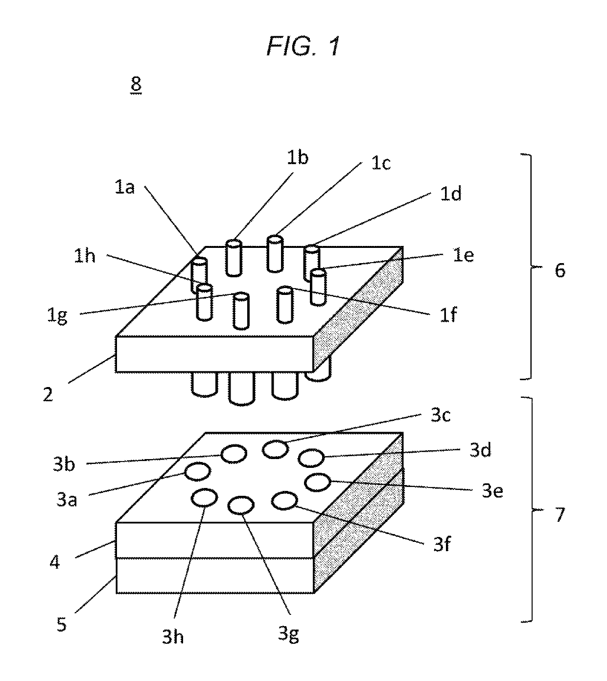
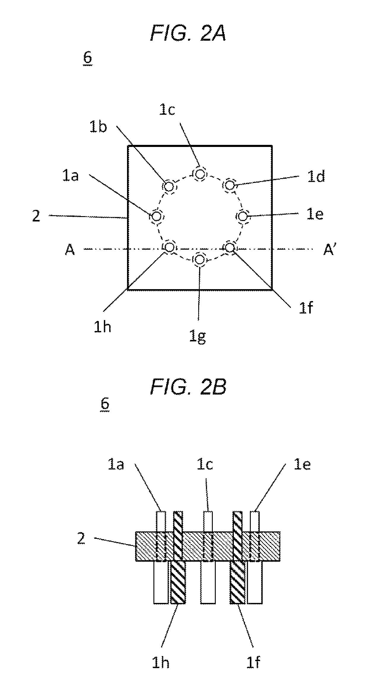
[Production of the First Electrode Unit 6]

[0068]The first electrodes 1a to 1h were produced with an iron, and were subjected to gold plating. Each of the first electrodes 1a to 1h was formed in a cylindrical shape with a diameter of 3 mm, and the eight first electrodes 1a to 1h were immobilized in a first insulator 2 made of a polyphenylene sulfide resin, along a concentric circle having a diameter of 30 mm.

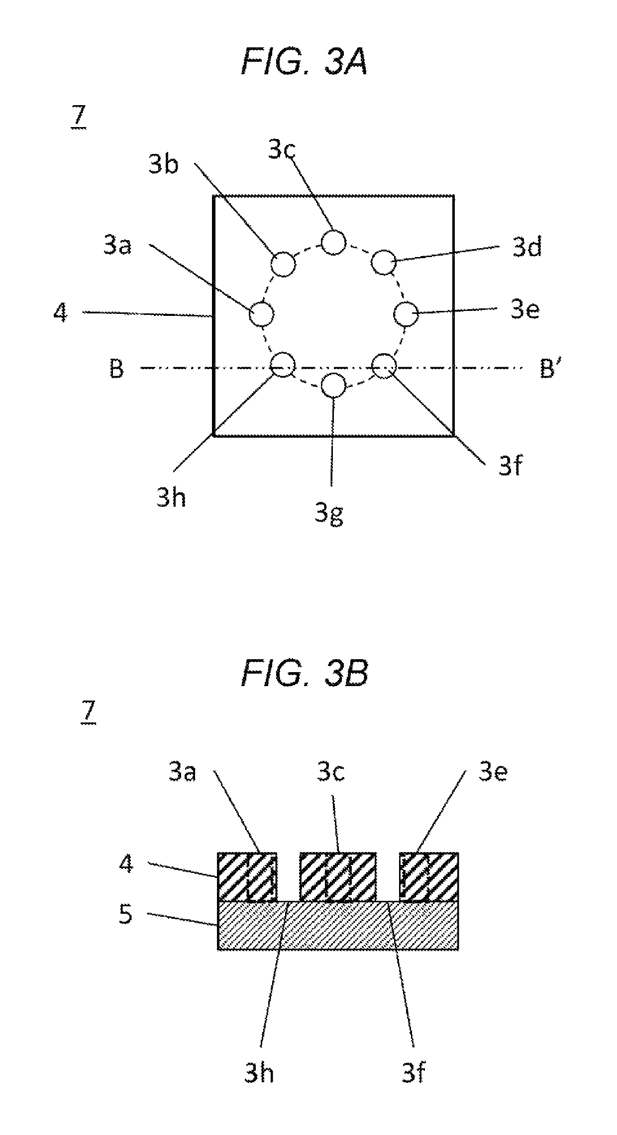
[Production of the Second Electrode Unit 7]

[0069]The second electrode 5 was produced with a sintered metal material (model number “ESS-40-40-1-2” manufactured by SMC CORPORATION), and was subjected to gold plating. Eight through-holes each having a diameter of 3 mm were formed in a second insulator 4 made of a polyphenylene sulfide resin, in a concentric pattern. The second electrode 5 and the second insulator 4 were immobilized to one another, and the above through-holes were employed as measurement chambers 3a to 3h.

[Loading of Measurement Samples]

[0070]A carbon black...

Example

EXAMPLE 2

[0079]Differences between EXAMPLE 2 and EXAMPLE 1 will be described. Unless otherwise specified, the same conditions as those in EXAMPLE 1 were adopted.

[Loading of Measurement Samples]

[0080]Platinum-supported carbon materials (model number “TEC10EA50E” manufactured by TANAKA KIKINZOKU KOGYO K.K.) were provided as measurement samples. 2.5 mg of the material was loaded into each of the measurement chambers 3a to 3h.

[Method for Varying Measurement Environments]

[0081]The air was supplied to the gas-flow channel to thereby convert the insides of the measurement chambers 3a to 3h to air-present environments, and then, measurements were conducted. Then, a hydrogen gas was supplied to the gas-flow channel to convert the insides of the measurement chambers 3 to hydrogen environments, and measurements were conducted. Results obtained through the measurements conducted by varying pressing conditions are shown in Table 2.

[0082]TABLE 2Pressing force (Mpa)12346810EXAMPLE 2In the airThic...


PUM


Abstract

Disclosed is a resistance-measurement apparatus, including: multiple measurement chambers for holding powdery materials; multiple first electrodes that press the respective powder materials in the measurement chambers; at least one second electrode that faces the first electrodes and that presses the powdery materials; and a measuring device that measures a resistance between the first electrodes and the at least one second electrode. Further disclosed is a resistance-measurement method, including: (i) placing at least one powdery material between a number N of first electrodes and at least one second electrode, and pressing the at least one powdery material therebetween; (ii) measuring an impedance between the number N of the first electrodes and the at least one second electrode; and (iii) measuring an impedance between a number M of the first electrodes and the at least one second electrode, wherein the number N is different from the number M.

Description

TECHNICAL FIELD[0001]The technical field relates to resistance-measurement apparatuses and methods. In particular, the technical field relates to resistance-measurement apparatuses and methods that are employed for evaluations of powdery materials.BACKGROUND[0002]In recent years, the importance of selection and rapid development of materials has increased, for the purposes of improving performance of products and speeding up their development time.[0003]Taking polymer electrolyte fuel cells (PEFCs) as an example, catalyst layers and gas-diffusion layers are joined in sequence onto both outer surfaces of electrolyte membranes in which power-generation reactions occur, thereby forming membrane / electrode assemblies. Then, the membrane / electrode assemblies are each placed between separators to produce single cells, and a required number of the multiple single cells are stacked to produce polymer electrolyte fuel cells.[0004]A fuel gas containing hydrogen, and an oxidant gas containing o...

Claims


Application Information

Patent Timeline
IPC IPC(8): G01N27/04G01N33/20G01N33/00
CPCG01N27/043G01N33/20G01N2033/0091
Inventor KIKUZUMI, SHINYAYOSHINO, SHINJI
Owner PANASONIC INTELLECTUAL PROPERTY MANAGEMENT CO LTD
Why Eureka
Try Eureka