Supercharge Your Innovation With Domain-Expert AI Agents!

Techniques for coating pipes

a technology of coating pipes and pipes, applied in the direction of insulation, mechanical equipment, borehole/well accessories, etc., can solve the problems of pipe not being regarded in the industry as being ‘flexible’, irreversible damage to the structure, and steel plastic deformation

Active Publication Date: 2019-06-04
ACERGY FRANCE
View PDF35 Cites 0 Cited by
  • Summary
  • Abstract
  • Description
  • Claims
  • Application Information

AI Technical Summary

Benefits of technology

The invention is an insulating insert that is placed around the joint of a pipeline to insulate it. The insert is made up of curved segments of insulating material that are connected by flexible links. This allows the insert to bend easily along its length, which is useful when the pipeline needs to be bent to follow its route.

Problems solved by technology

Yet, such pipes are not regarded in the industry as being ‘flexible’.
Exceeding that limit causes irreversible damage to the structure.
Exceeding this limit caused plastic deformation of the steel.
The waxes, asphaltenes, hydrates or other solid condensates that appear as a result may clog the pipeline and are difficult to remove.
Otherwise, cold spots may arise that could promote clogging of the pipeline by solid condensates.
A design constraint particularly of reel-lay pipelines is that the outer diameter of the field joint coating cannot be significantly different to the outer diameter of the parent coatings on the adjacent pipe joints.
Also, the parent coating and the field joint coating are sufficiently compatible that they fuse together at their mutual interface, resisting cracking and hence giving longer service life.
In principle, S-lay allows faster pipelaying than J-lay but J-lay is necessary in challenging situations where water depth and strong currents make S-lay impractical without imparting large strains to the pipeline.
Otherwise there will be a ‘bottleneck’ in the pipeline installation process.
It follows that delays in welding and field joint coating operations may also affect reel-lay operations, specifically the time that is required to load a pipeline onto a reel-lay installation vessel when that vessel visits a spoolbase.
Delays also increase operational costs of the vessel that may accumulate at a rate of hundreds of thousands of US dollars per day.
Delays also risk missing a weather window during which the pipeline can be laid in a satisfactory sea state, which could delay the entire subsea installation project at even greater expense.
It will be apparent that whether S-lay, J-lay or reel-lay methods are employed to lay rigid pipe, the pipeline—including each of its successive field joint coatings—will experience substantial stresses and strains.
However, stresses and strains are particularly prevalent before and during laying as the pipeline is deflected onto a reel, over an overbend or through a sag bend, as the case may be, during spooling or laying.
When a pipeline undergoes substantial bending, cracks will tend to appear and de-bonding will tend to occur at the interfaces between field joint coatings and parent coatings.
The presence of an insert adds further interfaces and gives rise to additional stress and strain concentrations within the field joint coating, which increases the risk of cracks appearing.
Any such cracks may allow water to reach the outer surface of the steel pipe, thus corroding the pipe.
Water ingress may also reduce the adhesion of the coatings to the pipe and may additionally degrade the coatings themselves.
Degradation or loss of adhesion of the coatings will tend to permit further corrosion of the pipe and to lead to a failure of thermal insulation.
Disadvantageously, both of those solutions increase the time required to produce the field joint coating.
Whilst they provide effective thermal insulation and do not extend the cycle time unduly, their stiffness leads to high stresses in the field joint coating that may initiate cracks and lead to failure of the coating.
More generally, their stiffness unhelpfully modifies the local bending behaviour of the pipeline, which gives rise to stress concentrations upon bending because the stiffness of the pipeline and particularly of its coatings is not consistent along its length.

Method used


Image

  • Techniques for coating pipes
  • Techniques for coating pipes
  • Techniques for coating pipes

Examples


Embodiment Construction

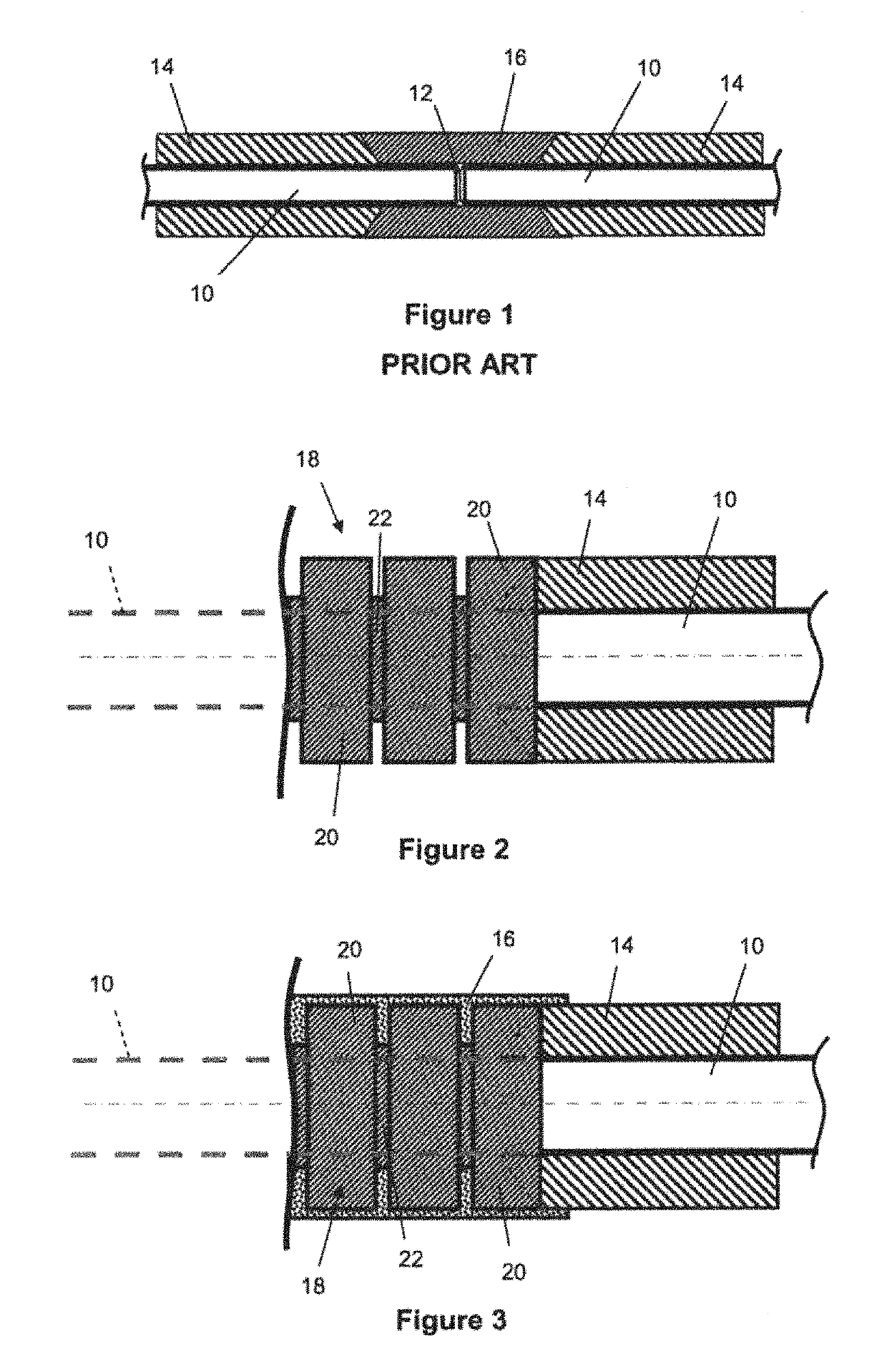
[0091]In the prior art arrangement shown in FIG. 1, a field joint is created between abutting pipe joints 10 of a pipeline, where a circumferential butt weld 12 attaches the pipe joints 10 to each other end-to-end. Each pipe joint 10 is coated with an insulating parent coating 14, for example a 5LPP coating, that terminates short of the facing end of each pipe joint 10 with a typically chamfered end shape. An annular gap lies between the opposed chamfered ends of the parent coatings 14 around the weld 12, where the exposed external surfaces of the pipe joints 10 are coated with an insulating field joint coating 16 that substantially matches the radial thickness of the parent coatings 14.

[0092]In this description, references to the radial direction are defined with respect to the central longitudinal axis of a pipe joint 10, which is also the centre of curvature of the pipe joints 10, the coatings 14, 16 and other tubular or part-tubular features.

[0093]As acknowledged in the introduc...


PUM


Abstract

An insulating insert is positioned around a field joint of a pipeline to insulate the field joint. The insert has a longitudinal series of annular or part-annular filler segments of insulating material, curved about a longitudinal axis, that are each joined to one or more adjacent segments of the series by at least one link. The links may be webs, rods, or articulated links. The links are flexible relative to the segments to facilitate bending of the insert along its length by enabling relative angular displacement between adjacent segments of the series.

Description

CROSS-REFERENCE TO RELATED APPLICATIONS[0001]This Application claims priority to Great Britain Application Number 1423241.8 filed on Dec. 24, 2014, and is a continuation-in-part application of U.S. application Ser. No. 13 / 808,570, which is the U.S. National Phase of International Application Number PCT / IB2011 / 001859 filed on Jul. 4, 2011, which claims priority to Great Britain Application Number 1106690.9 filed on Apr. 20, 2011, and Great Britain Application Number 1011283.7 filed on Jul. 5, 2010.[0002]This invention relates to coated pipelines and in particular to insulating inserts or infills for field joints of coated rigid pipelines, as used in the subsea oil and gas industry.BACKGROUND OF THE INVENTION[0003]Rigid subsea pipelines are commonly formed of lengths of steel pipe—‘pipe joints’—that are welded together end-to-end. Pipe joints are typically about 12 m in length but may be manufactured in multiples of that length, such as double, triple or quad pipe joints. To mitigate ...

Claims


Application Information

Patent Timeline
Patent Type & Authority Patents(United States)
IPC IPC(8): F16L59/20F16L13/02F16L58/18E21B17/04E21B17/01E21B36/00
CPCE21B17/04E21B17/015F16L59/20F16L13/0272F16L58/181E21B36/003
Inventor HOFFMANN, PHILIPPE
Owner ACERGY FRANCE
Features
  • R&D
  • Intellectual Property
  • Life Sciences
  • Materials
  • Tech Scout
  • Unparalleled Data Quality
  • Higher Quality Content
  • 60% Fewer Hallucinations
Learn More