
Torsional orthopaedic revision system

a technology of orthopaedic revision and torsional articulation, which is applied in the field of improved surgical equipment, can solve the problems of significant accidental damage to adjacent bone of the walls of the femur, difficult removal of an implant secured by ingrowing bone, and long life of the recipient, so as to reduce the distal diameter

Active Publication Date: 2019-06-25
RADLEY SCI LTD
View PDF6 Cites 1 Cited by
  • Summary
  • Abstract
  • Description
  • Claims
  • Application Information

AI Technical Summary

Benefits of technology

The patent describes a device that uses a waveguide to amplify the intensity of ultrasonic vibrations at the distal end of the device. This is accomplished by reducing the diameter of the waveguide in that area. The technical effect is that the device can better transmit ultrasonic vibrations to the target area, resulting in improved performance.

Problems solved by technology

However, this is not a drawback, as the healed bone surrounding the implant holds it in place under compression, and at worst the implant may shift in position millimetrically, to seat further into the cavity or to reach a less stressed position for example.
Prostheses such as femoral implants are durable, but can fail, and the lifetime of the recipient is nowadays very often longer than that of the implant.
At this point, removal of an implant secured by ingrowing bone can be difficult, and it is necessary to chisel or cut down through this bone, around the implant shaft (or a stub left by a fractured implant shaft).
This is a lengthy and tiring process for both patient and surgeon, and can result in significant accidental damage to adjacent bone of the walls of the femur.
However, such tools are still far from perfect, and surgeons would always benefit from using tools that operate more rapidly, more accurately, more controllably and / or with less effort.
This is again a tedious process, especially adjacent a distal end of the cavity, where the cement tends to form a solid terminal plug rather than a thin layer around the cavity walls.
Additionally, longitudinal-mode ultrasonic vibrations, directed along a probe or tool shaft, can lead to problems, as they characteristically have a distal extensional drilling effect, whether required or not, and they project ultrasound energy a considerable distance longitudinally from a distal tip of the tool / probe.
This can lead to tissue damage away from the implant site, and can result in physical bone penetration by said distal tip, even with feedback monitoring to halt such effects by spotting the resonance frequency changes that would occur.
The geometry of the skeleton and surrounding body tissues may in any case make access to a bone cavity difficult, especially if one is trying to operate along the cavity.
The dimensions and configuration of the stack and horn significantly affect the resonant frequencies and vibrational amplitudes that can be created in a tool, but unfortunately, many current systems thus inevitably have heavy and bulky stack / horn units which the surgeon must hold and manipulate until the tool can be aligned to act on the desired tissues (or bone or cement, as appropriate).
Lastly, the precision required of a surgeon can become unreasonable.
For example, when working longitudinally down a cavity, through bone holding an implant to an interior of a femur, a very slight inaccuracy could lead to the tip of the tool veering outwardly and damaging the bone of the femoral wall, or alternatively slanting inwardly and contacting the implant, potentially damaging the tool.

Method used


Image

  • Torsional orthopaedic revision system
  • Torsional orthopaedic revision system
  • Torsional orthopaedic revision system

Examples


Embodiment Construction

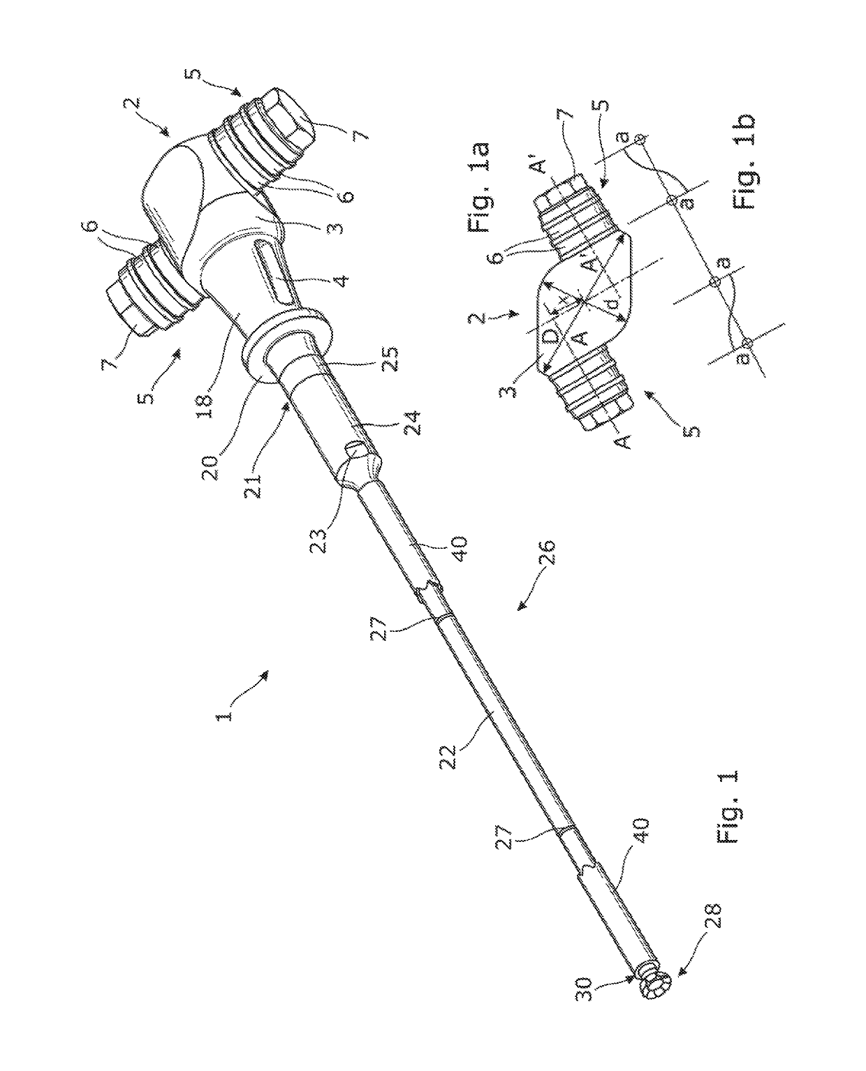
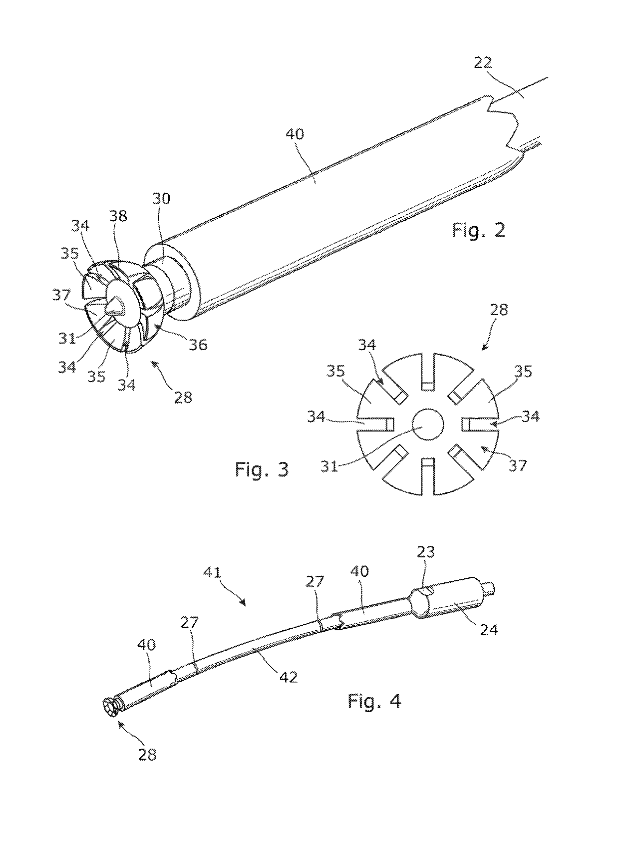
[0090]Referring now to the Figures, and to FIG. 1 in particular, a first surgical tool 1 provided with a torsional mode oscillatory system comprises an ultrasonic transducer unit 2, disposed at a proximal end of the tool 1. The transducer unit 2 comprises a torsional converter body 3, to which are mounted a pair of axial-mode ultrasonic transducer stacks 5, each made up of a plurality of axially-polarised piezo-electronic ceramic rings 6, separated by metal electrode rings alternating with the piezo-electric ceramic rings 6 along a central shaft of a threaded bolt 7. The axial-mode ultrasonic transducer stacks 5 are mounted in symmetrical opposition on opposite sides of the torsional converter body 3, at points separated by 180° around its circumference.

[0091]As shown, the axial-mode ultrasonic transducer stacks 5 are each mounted to extend outwards, perpendicularly to a longitudinal axis of the transducer unit 2 and a remainder of the tool 1. However, while a longitudinal axis of e...


PUM


Abstract

A torsional-mode ultrasonic vibration generator is manufactured with longitudinal slots extending along its horn which damp unwanted vibrational modes and allow it to be made significantly smaller than previous apparatus. The torsional-mode ultrasonic generator is operable with a suite of surgical tools, to perform portions of an orthopaedic arthroplasty revision procedure. Three of the tools are for removing bone cement from within a bone cavity on a prosthesis cemented into the bone cavity. Three other tools are for separating an uncemented prosthesis from ingrown bone by cutting the bone between the prosthesis and walls of the bone cavity. The seventh tool is provided with sensors to determine a separation between a bone-cutting tool head and a metal prosthesis, feedback from the sensors being used to control servo motors of an articulated mounting for the seventh tool, to maintain the separation at a desirable value.

Description

CROSS REFERENCE TO RELATED APPLICATIONS[0001]This application is the National Phase filing under 35 U.S.C. § 371 of International Application No. PCT / GB2015 / 000201, filed on Jun. 27, 2015, and published on Dec. 30, 2015 as WO / 2015 / 198005 A1, and claims priority to Great Britain Application No. 1411381.5, filed on Jun. 26, 2014. The contents of each of the prior applications are hereby incorporated by reference herein in their entirety.FIELD OF THE INVENTION[0002]The present invention relates to an improved system of surgical equipment for use in orthopaedic surgery. More particularly but not exclusively, it relates to ultrasonically-activatable tools and ultrasound generators for use in the revision of prosthesis implantation and trauma fixation.BACKGROUND ART[0003]Orthopaedic implants, such as femoral implants for hip joint replacements, are implanted using two main approaches. In one, a cavity within the femur is shaped to receive the shaft of the implant, and following implantati...

Claims


Application Information

Patent Timeline
Patent Type & Authority Patents(United States)
IPC IPC(8): A61B17/88A61B17/16A61B17/32A61F2/46
CPCA61B17/8847A61B17/164A61B17/320068A61B17/1659A61F2002/4683A61B2017/1602A61F2/36A61F2002/4619A61B2017/320098A61B2017/320089
Inventor YOUNG, MICHAEL JOHN RADLEYYOUNG, STEPHEN MICHAEL RADLEYEDE, MICHAEL JAMES
Owner RADLEY SCI LTD
Learn More