Engine and coolant system control systems and methods

a technology of coolant system and control system, which is applied in the direction of machines/engines, combustion air/fuel air treatment, mechanical equipment, etc., can solve the problems of shortening the life of engines, engine components, etc., and achieve the effect of increasing the flow rate of fuel

Active Publication Date: 2019-06-25
GM GLOBAL TECH OPERATIONS LLC
View PDF6 Cites 3 Cited by
  • Summary
  • Abstract
  • Description
  • Claims
  • Application Information

AI Technical Summary

Benefits of technology

[0004]Excessive heating may shorten the lifetime of the engine, engine components, and / or other components of a vehicle. As such, vehicles that include an internal combustion engine typically include a radiator that is connected to coolant channels within the engine. Engine coolant circulates through the coolant channels and the radiator. The engine coolant absorbs heat from the engine and carries the heat to the radiator. The radiator transfers heat from the engine coolant to air passing the radiator. The cooled engine coolant exiting the radiator is circulated back to the engine to cool the engine.SUMMARY
[0014]In further features, the ECM is configured to: increase the predicted value as the temperature of the fuel decreases; and decrease the predicted value as the temperature of the fuel increases.

Problems solved by technology

Excessive heating may shorten the lifetime of the engine, engine components, and / or other components of a vehicle.

Method used


Image

  • Engine and coolant system control systems and methods
  • Engine and coolant system control systems and methods
  • Engine and coolant system control systems and methods

Examples


Embodiment Construction

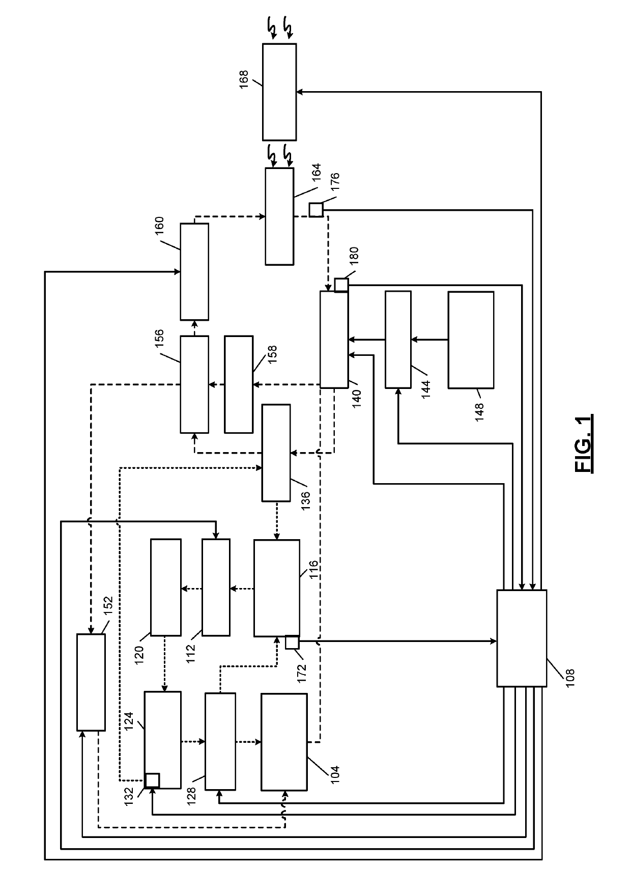
[0034]An engine combusts air and fuel to generate drive torque. For example, a diesel engine combusts air and diesel fuel within cylinders to generate drive torque. Combustion of air and fuel also generates heat and exhaust. Exhaust produced by the engine flows through an exhaust system before being expelled to atmosphere.

[0035]A diesel exhaust fluid (DEF) injector injects a DEF (e.g., urea) into the exhaust system to reduce the amount of one or more exhaust components (e.g., Nitrogen Oxides) before the exhaust is expelled to atmosphere.

[0036]A low pressure fuel pump pumps fuel from a fuel tank to a high pressure fuel pump. The high pressure fuel pump pumps fuel to a fuel rail. Fuel injectors inject fuel into cylinders of the engine from the fuel rail. A fuel regulator valve regulates fuel flow from the fuel rail back to the fuel tank. Fuel may also return to the fuel tank from the fuel injectors when insufficient power to open the fuel injectors is applied to the fuel injectors.

[00...


PUM


Abstract

A coolant control system of a vehicle includes a coolant pump that pumps coolant to a heat exchanger. A diesel exhaust fluid (DEF) injector injects a DEF into an exhaust system and receives coolant output from the heat exchanger. A fuel heat exchanger transfers heat between coolant and fuel flowing through the fuel heat exchanger. An engine control module is configured to determine a first requested speed for DEF injector cooling, determine a second requested speed for fuel cooling, and based on at least one of the first and second requested speeds, selectively increase at least one of: opening of a valve that controls a flow rate of fuel flowing from the fuel rail to the fuel tank, a flow rate of fuel from fuel injectors of an engine to the fuel tank, and a target speed of the coolant pump.

Description

INTRODUCTION[0001]The information provided in this section is for the purpose of generally presenting the context of the disclosure. Work of the presently named inventors, to the extent it is described in this section, as well as aspects of the description that may not otherwise qualify as prior art at the time of filing, are neither expressly nor impliedly admitted as prior art against the present disclosure.[0002]The present disclosure relates to internal combustion engines and more particularly to coolant and actuator control systems and methods.[0003]An internal combustion engine combusts air and fuel within cylinders to generate drive torque. Combustion of air and fuel also generates heat and exhaust. Exhaust produced by an engine flows through an exhaust system before being expelled to atmosphere.[0004]Excessive heating may shorten the lifetime of the engine, engine components, and / or other components of a vehicle. As such, vehicles that include an internal combustion engine t...

Claims


Application Information

Patent Timeline
Patent Type & Authority Patents(United States)
IPC IPC(8): F01P7/16F01P3/20F01N5/02F01P5/12F01P7/04F01P7/14F01P3/00
CPCF01P7/165F01P3/20F01P5/12F01P7/04F01P7/164F01P7/167F01N5/02F01P2007/146F01P2003/005F01P2005/125F01P2060/10F01P2060/16F01P2005/105F01P3/12F01N2610/02F01N2610/14F01N2610/11F01N2610/1433F02M31/20
Inventor LAROSE, JR., THOMASGIRARDI, NICHOLASSARSEN, DOUGLAS C.SMITH, MICHAEL A.
Owner GM GLOBAL TECH OPERATIONS LLC
Why Eureka
Try Eureka