Light converter and light source unit, and projector
a technology of light source unit and light converter, which is applied in the field of light source unit and light source unit, and projector, can solve the problems of reducing optical conversion efficiency, difficult to enhance luminance, and increasing so as to avoid reliability deterioration and increase the size of cooling system
- Summary
- Abstract
- Description
- Claims
- Application Information
AI Technical Summary
Benefits of technology
Problems solved by technology
Method used
Image
Examples
first embodiment
[1.1 Configuration]
(1.1.1 Configuration Example of Projector)
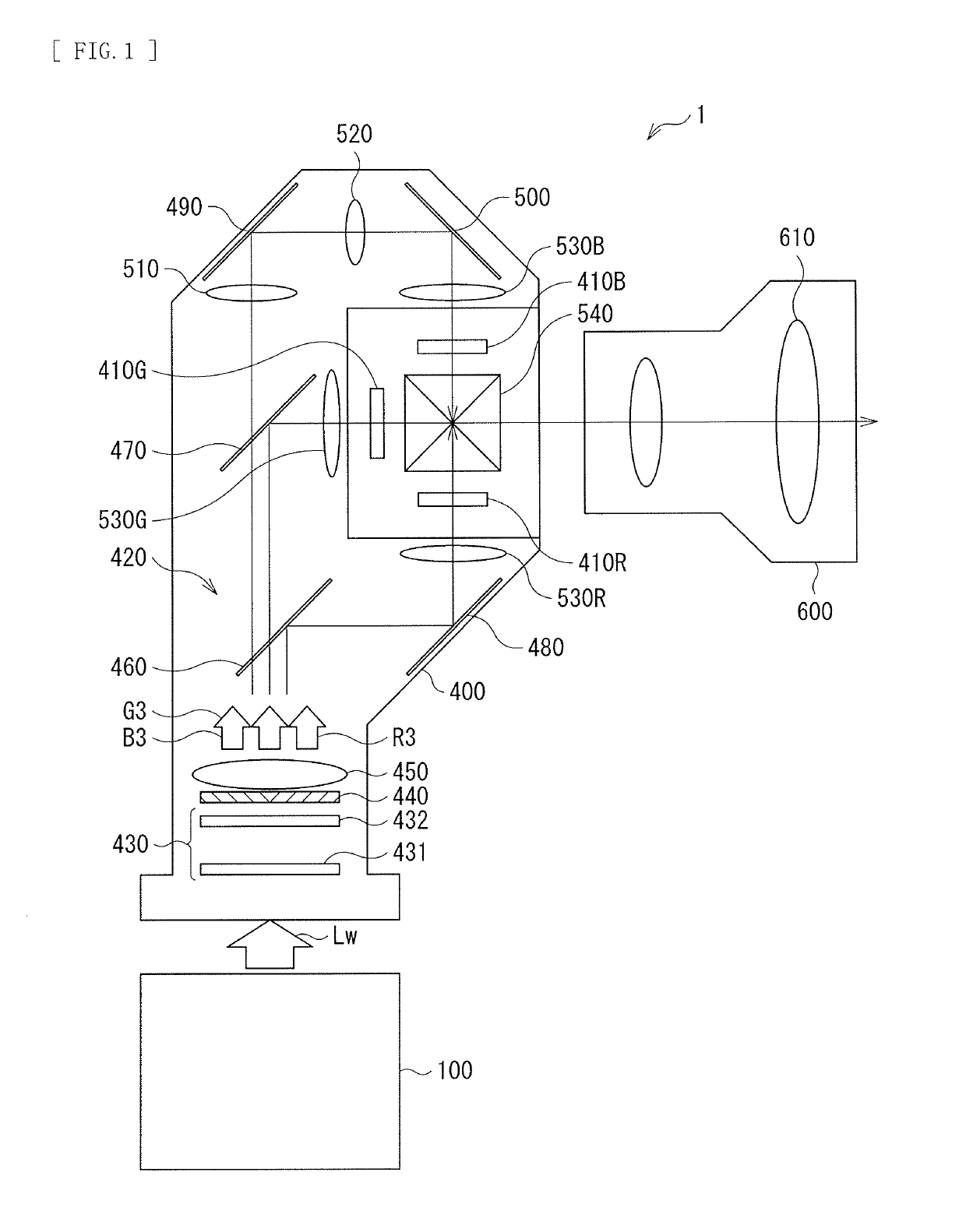
[0043]FIG. 1 illustrates a configuration example of a projector according to a first embodiment of the disclosure.
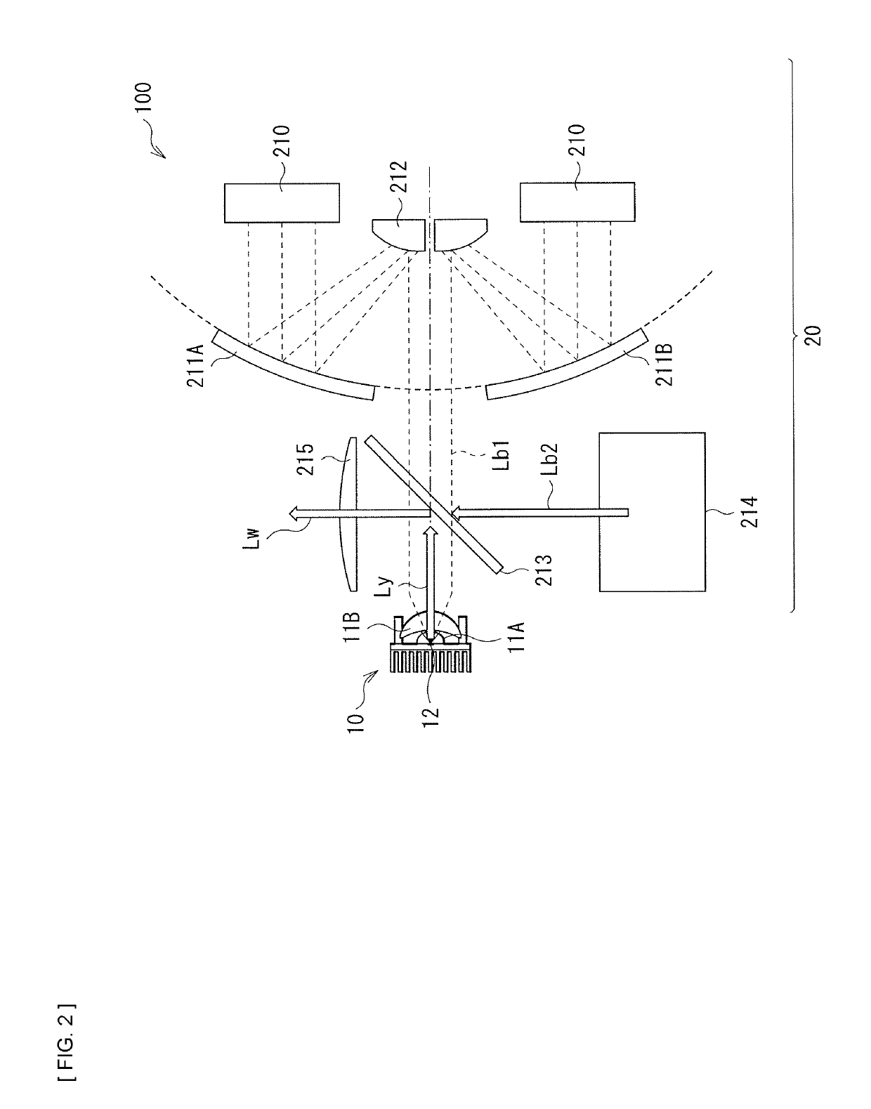
[0044]A projector 1 according to the present embodiment includes a light source unit 100; an image-generating system 400 that generates an image on the basis of light emitted from the light source unit 100; and a projection optical system 600. The image-generating system 400 has an image-generating section that generates an image on the basis of applied light, and an illuminating optical system 420 that irradiates the image-generating section with the light emitted from the light source unit 100.
[0045]The image-generating section has a light valve 410R for red, a light valve 410G for green, a light valve 410B for blue, and a dichroic prism 540 that synthesizes light from each of the light valves 410R, 410G and 410B. Each of the light valves 410R, 410G and 410B includes, for example, a transmissive liquid crysta...
second embodiment
[0087]Next, a description is provided of a second embodiment of the disclosure. Hereinafter, for parts having configurations and workings similar to those in the above-described first embodiment, the related descriptions are omitted as appropriate.
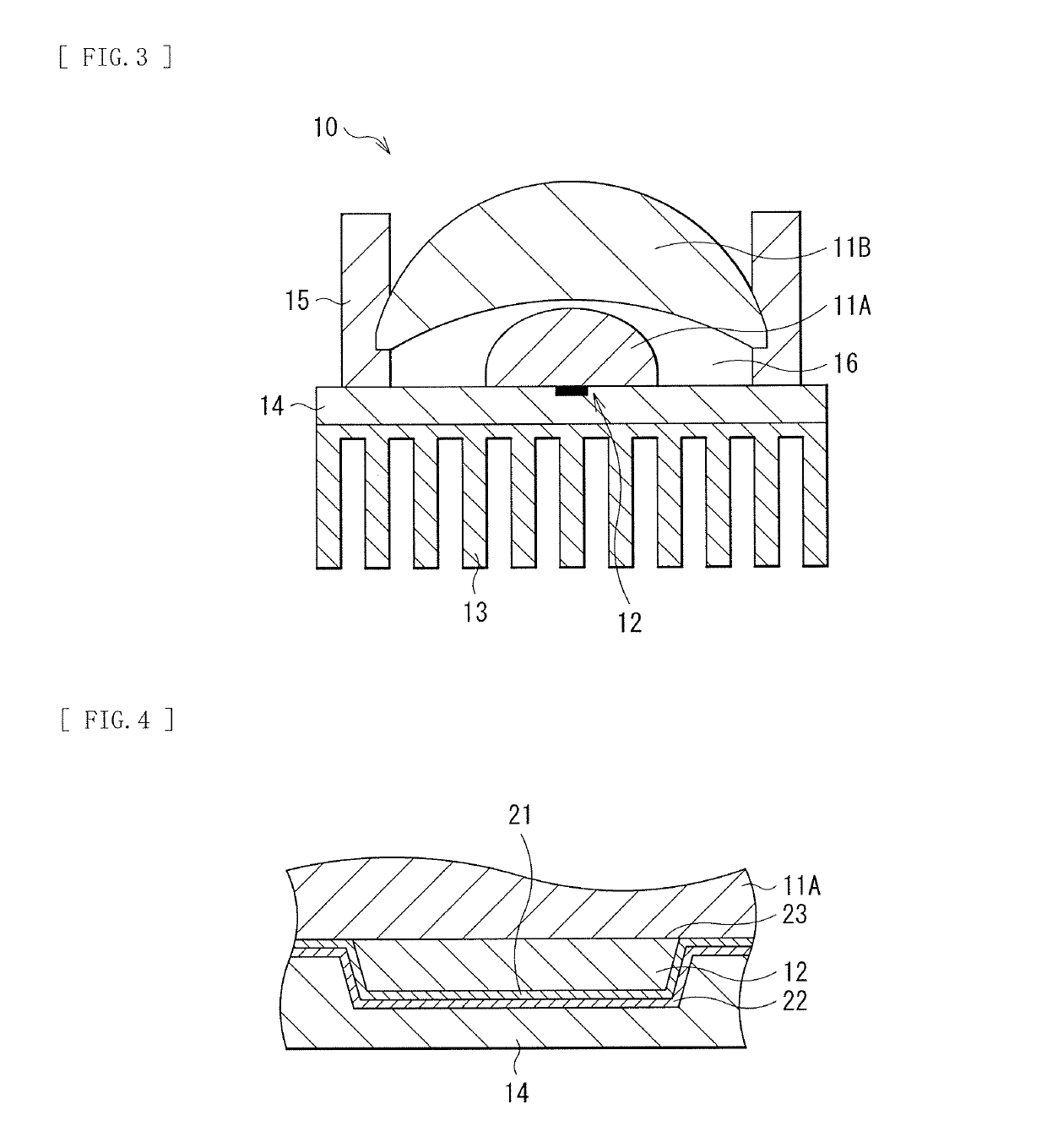
[0088]In the light converter 10 in the above-described first embodiment, all of the regions other than the region to which the fluorescent body 12 is bonded in the predetermined lens surface of the first light-collecting lens 11A are adhered to the heat spreader 14 serving as the heat-dissipating member. However, only a peripheral region of the region to which the fluorescent body 12 is bonded may be partially adhered to the heat spreader 14. With reference to FIGS. 6 to 9, a description is provided below of examples of such an adhesive structure.
[0089]It is to be noted that basic configurations of a projector and a light source unit according to the present embodiment may be substantially similar to those of the above-described first embo...
third embodiment
[0101]Next, a description is provided of a third embodiment of the disclosure. For parts having configurations and workings similar to those in the above-described first embodiment and the above-described second embodiment, the descriptions are omitted as appropriate below.
[0102]FIG. 10 illustrates a configuration example of a light converter 10D according to the third embodiment of the disclosure.
[0103]In the light converter 10 in the above-described first embodiment, the sealed structure is adopted for the space 16 between the first light-collecting lens 11A and the second light-collecting lens 11B. In contrast, in the light converter 10D according to the present embodiment, the lens holder 15 is provided with a passage hole through which a liquid coolant 24 passes, and a structure is adopted in which the liquid coolant 24 passes through the space 16 between the first light-collecting lens 11A and the second light-collecting lens 11B. Further, a structure may be adopted in which t...
PUM
 Abstract
Description
Claims
Application Information
 - R&D
- Intellectual Property
- Life Sciences
- Materials
- Tech Scout
- Unparalleled Data Quality
- Higher Quality Content
- 60% Fewer Hallucinations
Browse by: Latest US Patents, China's latest patents, Technical Efficacy Thesaurus, Application Domain, Technology Topic, Popular Technical Reports.
© 2025 PatSnap. All rights reserved.Legal|Privacy policy|Modern Slavery Act Transparency Statement|Sitemap|About US| Contact US: help@patsnap.com


