Mobility restraint device tensioner

a technology of restraint device and tensioner, which is applied in the direction of slip couplings, transportation items, couplings, etc., can solve the problems of inability to install current system tensioners, many vehicle retrofit opportunities pose difficult challenges, and limited clear aisle spacing, etc., to reduce the potential interference with existing fixed obstructions, reduce the footprint, and ensure the effect of installation and us

Active Publication Date: 2019-07-09
VALEDA
View PDF16 Cites 1 Cited by
  • Summary
  • Abstract
  • Description
  • Claims
  • Application Information

AI Technical Summary

Benefits of technology

[0011]Clearly, the prior art devices have limitations which the present embodiments overcome and make for more effective installation and use. For example, the new compact tensioner disclosed herein is thinner and has a smaller footprint, allowing it to be installed on the increasingly thinner seats and reduces the potential interference with existing fixed obstructions. In addition to the smaller size, the new compact tensioner offers a controllable amount of tension of the belt which results in consistent securement of the mobility device for a secure and comfortable ride. Current systems today often provide too much tension on the belt, or too little resulting on a very uncomfortable ride since the mobility devices will be moving side to side as the vehicle is moving.
[0015]Load limiting action: The device may be equipped with a load limiting device that controls the amount of tension / load that the operator can apply to the restraint and prevents excessive loading to the wheelchair and / or the tensioner.
[0016]A compact design (thinner, narrower & smaller footprint overall) may allow for easier and more flexible installation, in more applications / configurations, especially where space is limited, seats are very thin, or fixed obstructions exist like heating / cooling systems, wheel arches, etc. However, critical dimensions like belt opening location may be maintained to keep effective restraint angle. In addition, the compact design may allow for increased belt length which increases ease of securement with certain wheelchairs.
[0017]Safety unlock indicator: An indicator (visual or audible) may be used, which alerts the user when the device is not locked. This serves to let user know the system is ‘not’ locked / secured, which helps to prevent accidental release or a mobility device not being secured before being transported.
[0018]Simple / Intuitive Handle & Release: The handle is easy to use and operate. A release ‘button’ acts similar to parking brake, and as such is very intuitive. In some embodiments, no twisting is required to activate (i.e. no turning handle). A single button release reduces the knuckle clearance required, allowing for ‘tighter’ installations. By moving handle up and down, tension may be applied to the belt.

Problems solved by technology

Often times, two mobility device securement systems (i.e. Q'Pods) are installed side-by-side, and when occupied simultaneously by two mobility device passengers, the clear aisle spacing is limited or non-existent, which causes issues.
Also, many vehicle retrofit opportunities pose difficult challenges as there are often times existing fixed obstructions such as heating & cooling ducts and wheel-wells that are impossible or very costly to remove.
In these instances, current systems with tensioners are unable to be installed in these applications and the only current alternative is the traditional 4-point system which is less effective, especially in a city bus environment where limiting dwell times are critical.
In the Q'Pod's current design, twisting of handle is required to release the mechanism, which could be awkward for some users.
The overall size of the unit can create installation challenges especially in situations where there are ducts under the flip seats.
Finally, the tensioner does not provide a way to limit the amount of tension the user can exert on the restraint.

Method used


Image

  • Mobility restraint device tensioner
  • Mobility restraint device tensioner
  • Mobility restraint device tensioner

Examples


first embodiment

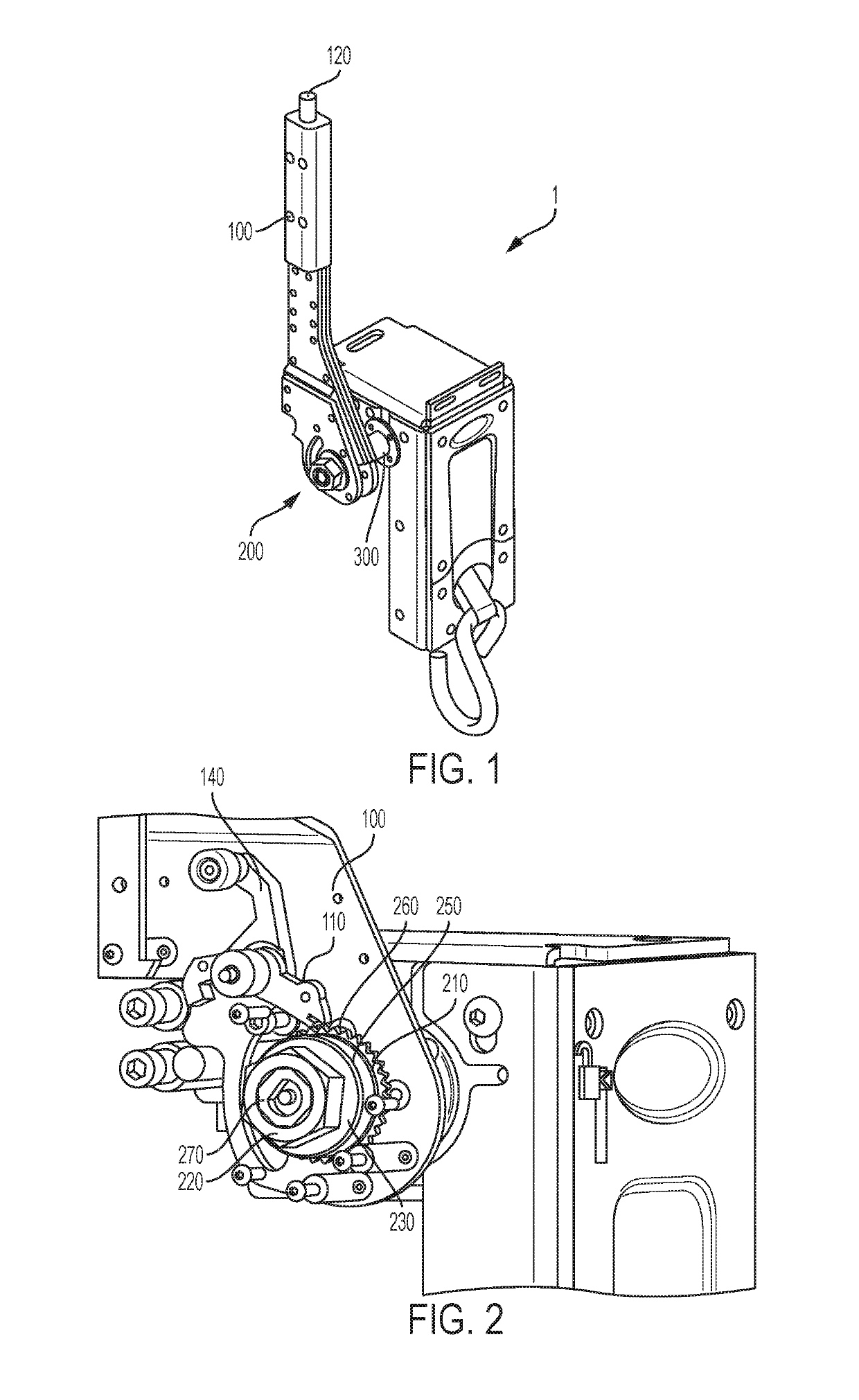
[0023]FIG. 1 is a perspective view of a tensioner;

[0024]FIG. 2 is a second perspective view of the first embodiment showing the clutch mechanism;

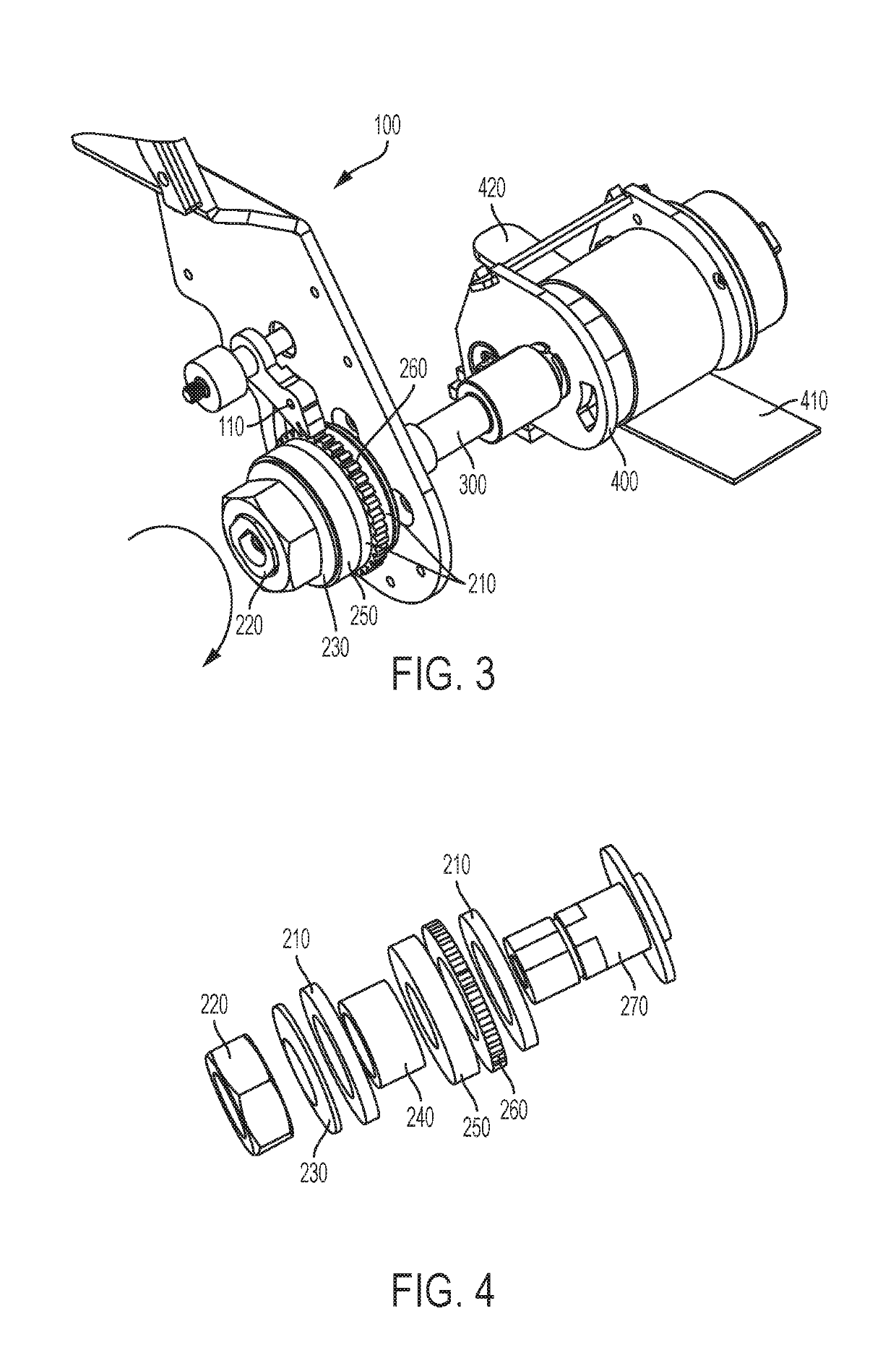
[0025]FIG. 3 is a third perspective view of the first embodiment showing additional components of the clutch mechanism;

[0026]FIG. 4 is an exploded view of the clutch mechanism for the first embodiment;

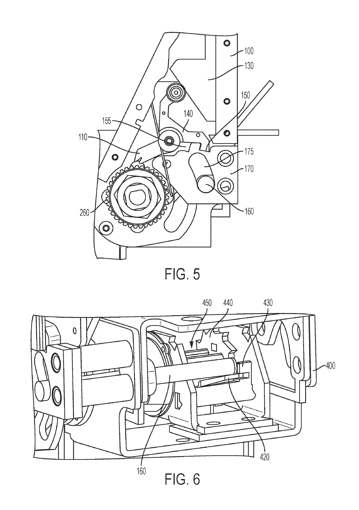
[0027]FIG. 5 is first side view of the first embodiment showing the release button mechanism in the stow mode;

[0028]FIG. 6 is a fourth perspective view of the first embodiment showing internal components of the release button mechanism in the stow mode;

[0029]FIG. 7 is a second side view of the first embodiment showing the release button mechanism in transition from the stow mode to the tension mode;

[0030]FIG. 8 is third side view of the first embodiment showing the release button mechanism in the tension mode;

[0031]FIG. 9 is a fourth side view of the first embodiment showing the safety indication mechanism in the stow mode;

[0032]FIG. 10 a fift...

second embodiment

[0033]FIG. 11 is a first side view of a tensioner in the stow mode;

[0034]FIG. 12 is a first front view of the second embodiment in the stow mode;

[0035]FIG. 13 is a second side view of the second embodiment in the tension mode;

[0036]FIG. 14 is a second front view of the second embodiment in the tension mode;

[0037]FIG. 15 is a first perspective view of the second embodiment showing the clutch mechanism; and,

[0038]FIG. 16 is a second perspective view of the second embodiment showing the safety indication mechanism.

[0039]It should be understood that the drawings are not necessarily to scale and that the embodiments are sometimes illustrated by graphic symbols, phantom lines, diagrammatic representations and fragmentary views. In certain instances, details which are not necessary for an understanding of the embodiments described and claimed herein or which render other details difficult to perceive may have been omitted. It should be understood, of course, that the inventions described h...


PUM


Abstract

A tensioning device is provided for tensioning a retractor in a wheelchair securement system. The tensioning device may include a clutch assembly for communicating rotational movement of a handle to a drive shaft operably connected to the spool of the retractor. The clutch assembly may include a pawl operably connected to the handle, which pawl communicates rotational movement of the handle to a drive sprocket. The clutch assembly may also include a friction member which communicates rotation of the drive sprocket to the drive shaft up to a predetermined amount of rotational force. If the rotational force exceeds the predetermined amount, the friction member will slip and cease to transfer rotational movement from the drive sprocket to the drive shaft. The clutch assembly may also include a compression member for compressing the friction member and drive sprocket whereby the predetermined amount of force may be adjusted.

Description

CROSS-REFERENCE TO OTHER APPLICATIONS[0001]This application claims priority to U.S. Provisional Patent Application No. 62 / 236,832, which was filed on Oct. 2, 2015; it is incorporated herein by reference. The disclosures of U.S. Pat. No. 9,107,786 and U.S. Patent Publication No. 2014-0334893 are also incorporated herein by reference.STATEMENT REGARDING FEDERALLY SPONSORED RESEARCH OR DEVELOPMENT[0002]Not Applicable.THE NAMES OF PARTIES TO A JOINT RESEARCH AGREEMENT[0003]Not Applicable.INCORPORATION-BY-REFERENCE OF MATERIAL SUBMITTED ON A COMPACT DISC[0004]Not Applicable.BACKGROUND[0005]Technical Field[0006]The embodiments described and claimed herein relate generally to securing a mobility device (e.g. wheelchair, scooter, stretcher, etc.) using a “tensioner” that induces tension into a restraint to provide greater stabilization while the mobility device is being transported in a vehicle (although it could be used to transport it outside of a vehicle). In one embodiment, the tensioni...

Claims


Application Information

Patent Timeline
Patent Type & Authority Patents(United States)
IPC IPC(8): A61G3/08F16D47/04B60P7/08F16D7/02F16D41/12B60R9/08B60P7/06
CPCA61G3/0808A61G3/0875B60P7/083F16D7/025F16D41/12F16D47/04B60R9/08B60P7/06
Inventor CARDONA, EDGARDOGIRARDIN, PATRICK
Owner VALEDA
Why Eureka
Try Eureka