Frequency monitoring of gradient pulses during magnetic resonance imaging

a magnetic resonance imaging and pulse technology, applied in the field of frequency monitoring of gradient pulses during magnetic resonance imaging, can solve the problems of significant mechanical force influences in the gradient system, significant technical problems, and correspondingly rapid change of gradient fields employed, and achieve precise prospective frequency monitoring, large influence on the increase of mechanical force flow, and the effect of carrying ou

Active Publication Date: 2019-07-09
SIEMENS HEALTHCARE GMBH
View PDF23 Cites 4 Cited by
  • Summary
  • Abstract
  • Description
  • Claims
  • Application Information

AI Technical Summary

Benefits of technology

[0016]Different effects can be achieved by the techniques described herein. Thus, it is possible, for example, to establish reliably, even before the MR measurement sequence is executed, whether an increased mechanical force flow in the gradient system is to be expected with the corresponding machine control parameters. The user of the MR system then can already react accordingly at the planning stage of the MR measurement sequence and carrying out the MR measurement sequence with corresponding potential loss of MR data can be prevented. A prospective frequency monitoring can thus be implemented. At the same time the frequency monitoring can be comparatively less computation-intensive, particularly in comparison to techniques in which an MR measurement sequence is checked computationally from resonance effects. The comparison with the reference data, i.e. with an empirical data basis, can be designed less computationally intensive. At the same time a learning procedure can be achieved. It is thus possible, by suitable maintenance of reference control parameters in the database that caused an MR measurement sequence to be aborted as a result of increased mechanical force flow, to constantly expand the data basis by storing further empirically-established-as-unsuitable reference control parameters. Thus a more precise frequency monitoring can be implemented.
[0021]As is evident from the above description, the type and number of machine control or reference control parameters is not especially restricted. Also, in view of this factor, it can be possible—via the identity comparison discussed above, if necessary taking account of tolerances—to implement more comprehensive techniques as part of the comparison of the machine control parameters with the reference control parameters. For example, such techniques can result in a more precise prediction of whether an increased mechanical force flow is to be expected in the gradient system.
[0022]Thus, for example, the comparison can include determining a measure of distance between the machine control parameters and the reference control parameters and making a threshold value comparison of the specific measure of distance with a predefined threshold value. The selective execution of the MR measurement sequence can take place as a function of a result of the threshold value comparison. In other words, the measure of distance can designate a metric that is defined in the area of the machine control and reference control parameters. Depending on whether the threshold value comparison has a positive or negative result, the MR measurement sequence can be executed or not. In particular, as part of the measure of distance, a specific weighting of the different types of machine control and reference control parameters can take place. The use of a measure of distance allows more precise account to be taken of the similarity or dissimilarity between the machine control and reference control parameters.
[0025]This can be based on the knowledge that the echo time TE, the repetition time TR and the number of slices of measured slices have an especially large influence on the increased mechanical force flow in the gradient system, particularly in comparison to the other aforementioned machine control or reference control parameters. Therefore, it can be worth making the effort to dimension the corresponding tolerance range within which the carrying out of the MR measurement sequence is prevented, comparatively small for the echo time TE, the repetition time TR and the number of slices of measured slices, in order to not unnecessarily prevent the carrying out of an MR measurement sequence. By means of such techniques, an especially precise prospective frequency monitoring can take place. In particular, it can be predicted especially well whether, with given machine control parameters, an increased mechanical force flow in the gradient system when carrying out the MR measurement sequence will result.
[0026]It can also be possible that a relative deviation of any given machine control parameter in relation to the corresponding reference control parameter, which is greater than a further predetermined threshold value, has the effect that the execution of the MR measurement sequence takes place. In other words, even if the other machine control parameters are identical, the MR measurement sequence can be executed provided in each case one machine control parameter deviates sufficiently from the corresponding reference control parameter. This is based on the knowledge that it is not possible always, or only possible to a restricted extent, to predict the increased mechanical force flow in the gradient system when executing the corresponding MR measurement sequence, provided only one machine control parameter also deviates significantly from the corresponding reference control parameter which indicates the increased mechanical force flow. By such techniques a reliable frequency monitoring can take place that does not excessively sensitively suppress the execution of the MR measurement sequence.
[0027]The determination of the measure of distance can further include an weighted averaging of the relative deviations of the machine control parameters in relation to the corresponding reference control parameters. In particular different weights can be used as part of the weighted averaging for the different machine control or reference control parameters. For example, in accordance with the above-mentioned exemplary embodiment, an especially heavy weighting could be given for the echo time TE, the repetition time TR and the number of slices of measured slices, especially by comparison with the weighting of the other machine control or reference control parameters. The weighted averaging allows an especially precise gradation of the influence of the different machine control parameters on the selective execution of the MR measurement sequence. This enables an especially precise prospective frequency monitoring to take place.

Problems solved by technology

Such currents, or comparably high currents that flow through the gradient coils—especially in conjunction with gradient pulses switched rapidly over time—can give rise to significant technical problems.
The rapid switching of the gradient pulse results in a correspondingly rapid change in the gradient fields employed.
The strong and rapid change of these magnetic fields over time typically result in significant mechanical force influences in the gradient system.
This frequently results in vibrations and mechanical distortions of the gradient coils, thus generally in mechanical force paths, which can be transmitted to surrounding components of the magnetic resonance system.
As a result of such mechanical force paths, a large amount of noise can develop in and around the magnetic resonance system.
The result is noise stress for the patient, so that countermeasures can be necessary, otherwise the comfort of the patient is reduced.
Thus, in such a case, the result can be an especially large amount of noise developing, strong vibrations, or an increased amount of heat developing.
Such known techniques have the disadvantage that the frequency spectrum that is excited by the timing sequence of the gradient pulses is able to be computed only to a limited extent, or with comparatively high computing outlay.
This can restrict the practicality of such techniques, especially with limited resources as regards computing capacity and / or time.
Such aborting of the carrying out of the MR measurement sequence can be disadvantageous for the performance of the MR system.
Thus, MR data acquired before the sequence abortion can become unusable and it can be necessary subsequently to create a new MR measurement sequence.
All this can be time-intensive and susceptible to errors.
If, for example, the MR measurement sequence is not changed sufficiently, or the same MR measurement sequence is carried out again at a later point in time (for example by another user), then the same error can occur once again.

Method used


Image

  • Frequency monitoring of gradient pulses during magnetic resonance imaging
  • Frequency monitoring of gradient pulses during magnetic resonance imaging
  • Frequency monitoring of gradient pulses during magnetic resonance imaging

Examples


Embodiment Construction

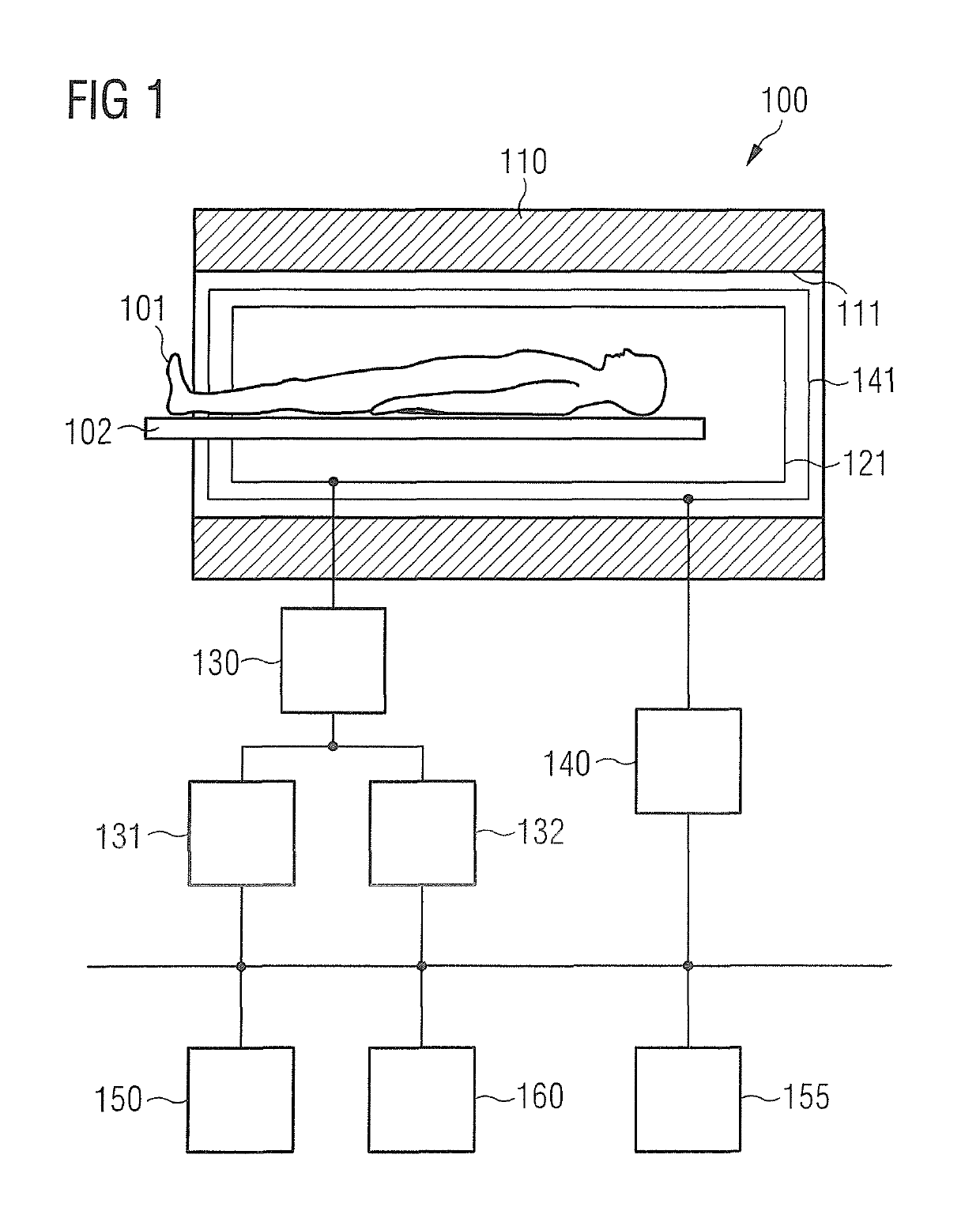
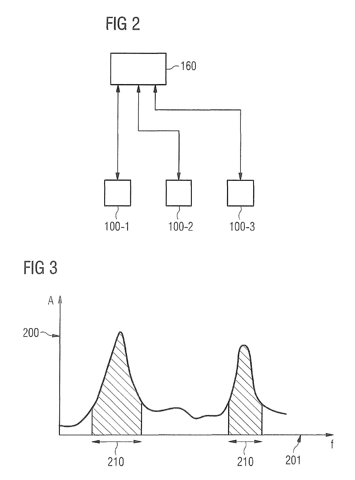
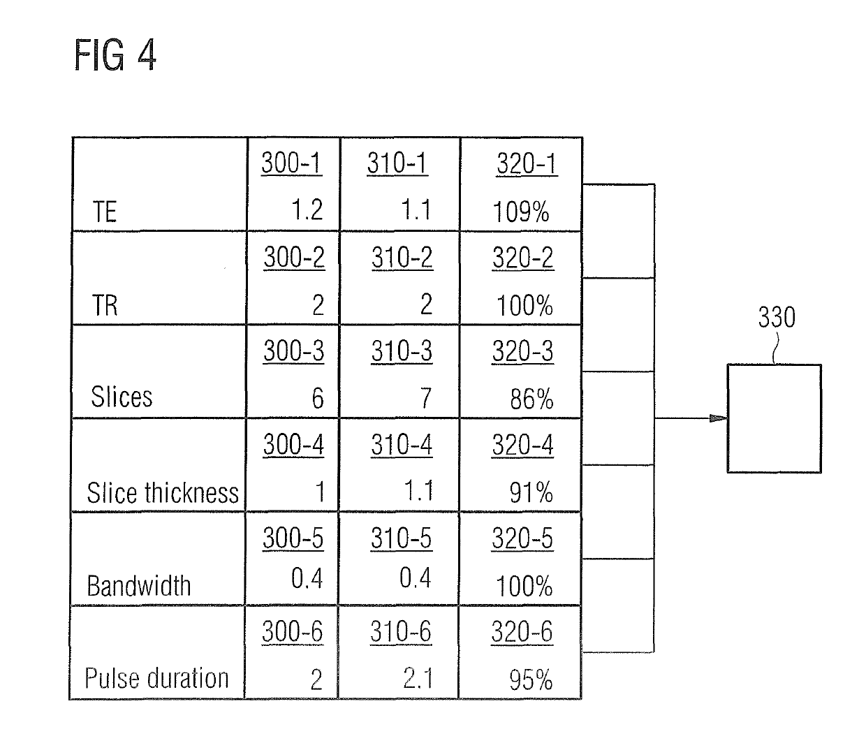
[0038]The present invention is explained in greater detail below on the basis of preferred forms of embodiment which refer to the drawings. In the figures the same reference characters designate the same or similar elements. The figures are schematic representations of different forms of embodiment of the invention. Elements presented in the figures are not necessarily presented true-to-scale. Instead the various elements shown in the figures are reproduced such that their function and general purpose is understandable to the person skilled in the art. Connections and couplings between functional units shown in the figures can also be implemented as indirect connections or couplings. A connection or coupling can be implemented hard-wired or wirelessly. Functional units can be implemented as hardware, software or as a combination of hardware and software.

[0039]Techniques for frequency monitoring of a timing sequence of gradient pulses in MR imaging are explained below. Before an MR m...


PUM


Abstract

Machine control parameters of a magnetic resonance apparatus are selected that influence the timing sequence of gradient pulses of the system's gradient system when a magnetic resonance measurement sequence is executed. The machine control parameters are compared with reference control parameters that indicate an increased mechanical force flow in the gradient system when the MR measurement sequence is being executed. As a function of the comparison, the MR measurement sequence is executed selectively with the selected machine control parameters.

Description

BACKGROUND OF THE INVENTION[0001]Field of the Invention[0002]The invention concerns techniques for selectively carrying out a magnetic resonance measurement sequence with specific machine control parameters of a magnetic resonance system, as a function of a comparison of the machine control parameters with reference control parameters that are stored in a database.[0003]Description of the Prior Art[0004]An MR measurement sequence is typically carried out as part of magnetic resonance (MR) imaging. The MR measurement sequence includes—as well as radio frequency pulses and read-out windows, for example—the switching (activation) of gradient pulses of a gradient system, i.e. the time-dependent application of gradient fields by feeding power to gradient coils of a gradient system. The switching of the gradient pulses typically enables local encoding of the MR data acquired as part of MR imaging to be achieved. With typically dimensioned gradient systems it can be necessary for currents ...

Claims


Application Information

Patent Timeline
Patent Type & Authority Patents(United States)
IPC IPC(8): A61B5/055G01R33/54G01R33/385
CPCG01R33/543G01R33/3854G01R33/385A61B5/055
Inventor GRODZKI, DAVID
Owner SIEMENS HEALTHCARE GMBH
Why Eureka
Try Eureka