
Method and apparatus for describing the statistical orientation distribution of particles in a simulation of a mould filling process

a particle and statistical orientation technology, applied in the field of methods and apparatus for describing the statistical orientation distribution of particles in the simulation of a mould filling process, can solve the problems of insufficient accuracy of simulation, significant complexity of simulation and belonging equation set, and inability to introduce a 3-d simulation process successfully. , to achieve the effect of less computation intensiv

Active Publication Date: 2013-01-29
MAGMA GIESSEREITECH
View PDF25 Cites 3 Cited by
  • Summary
  • Abstract
  • Description
  • Claims
  • Application Information

AI Technical Summary

Benefits of technology

This method reduces computational effort and provides stable results for predicting fibre orientation distribution and thermo-mechanical properties, enabling optimization of fibre-reinforced plastic components in terms of strength and shape stability.

Problems solved by technology

When particles, such as fibres, are added to the polymer composition, and the orientation distribution of the fibres needs to be described, the simulation and belonging equation set becomes significantly more complex.
True 3-D simulation of such a process has hitherto not been introduced successfully on the workplace since the complexity of the simulation would not allow acceptable results on present day workstations, since either the computation time would be too long, or the accuracy of the simulation would be inadequate.
When the need for component or mould configuration modifications are discovered late in the design development process, the delay and associated costs to implement the necessary changes are significantly higher than in earlier stages of the design development stages.
However, it is important to note that this system could not be described as truly three-dimensional because the model cannot simulate velocity components in the out of plane direction (a limitation of the Hele-Shaw approximation).
The method described in this document would, when adapted to true three-dimensional simulation, result in a unstable and too much processing power consuming simulation that could not be used in the workplace of e.g. development engineers.

Method used


Image

  • Method and apparatus for describing the statistical orientation distribution of particles in a simulation of a mould filling process
  • Method and apparatus for describing the statistical orientation distribution of particles in a simulation of a mould filling process
  • Method and apparatus for describing the statistical orientation distribution of particles in a simulation of a mould filling process

Examples


Embodiment Construction

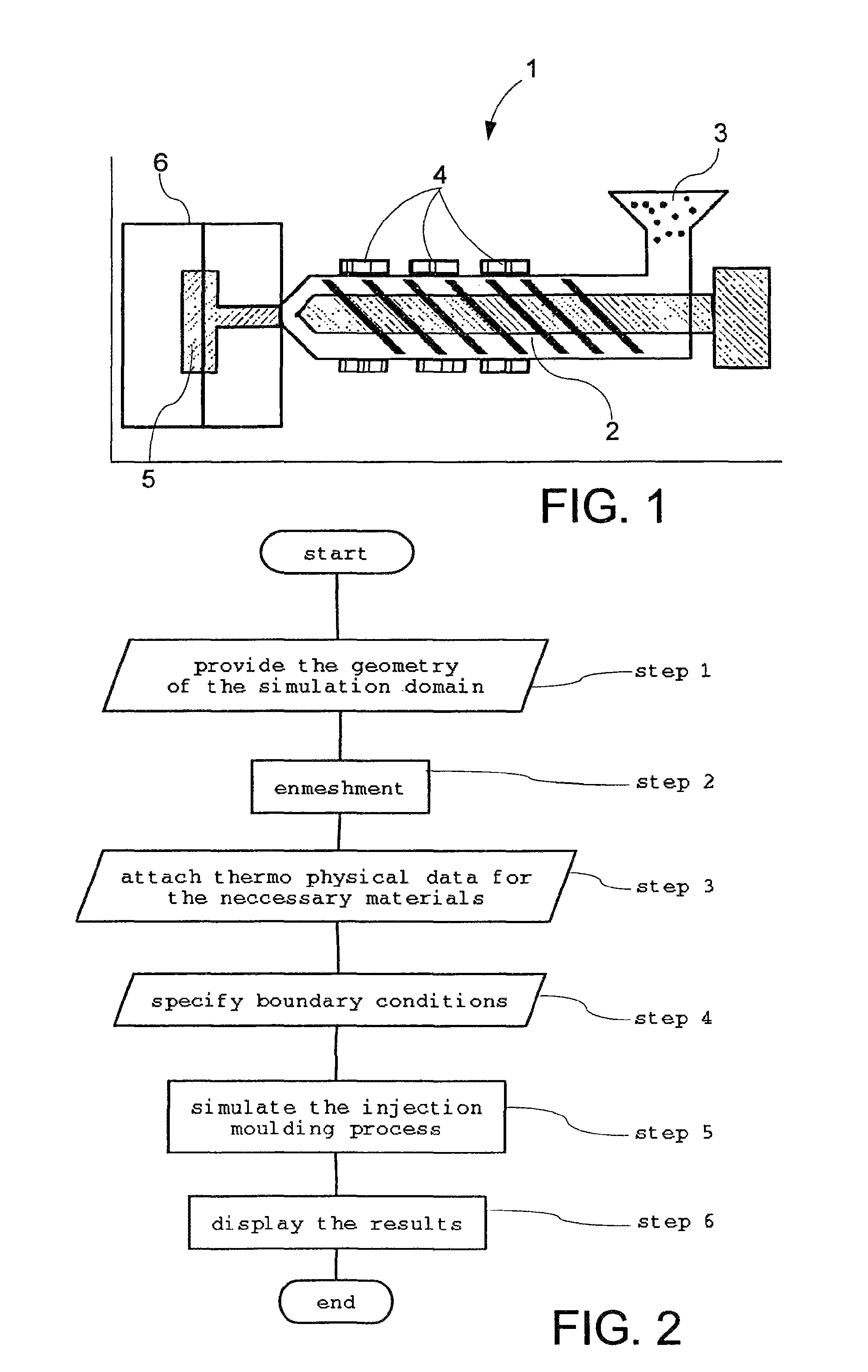
[0037]FIG. 1 shows diagrammatically an injection moulding machine 1. The injection moulding machine is provided with a screw 2 that is fed with polymer pellets disposed in a hopper 3. The polymer pellets are by the action of the screw 2 and heating elements 4 transformed to a viscous mass that is urged under high pressure into a mould cavity 5 in the mould 6. And moulding machine and the injection moulding manufacturing cycle are well-known in the art and not explained in the detail here. With the moulding machine 1 both non-fibre reinforced and fibre reinforced plastic parts can be manufactured.

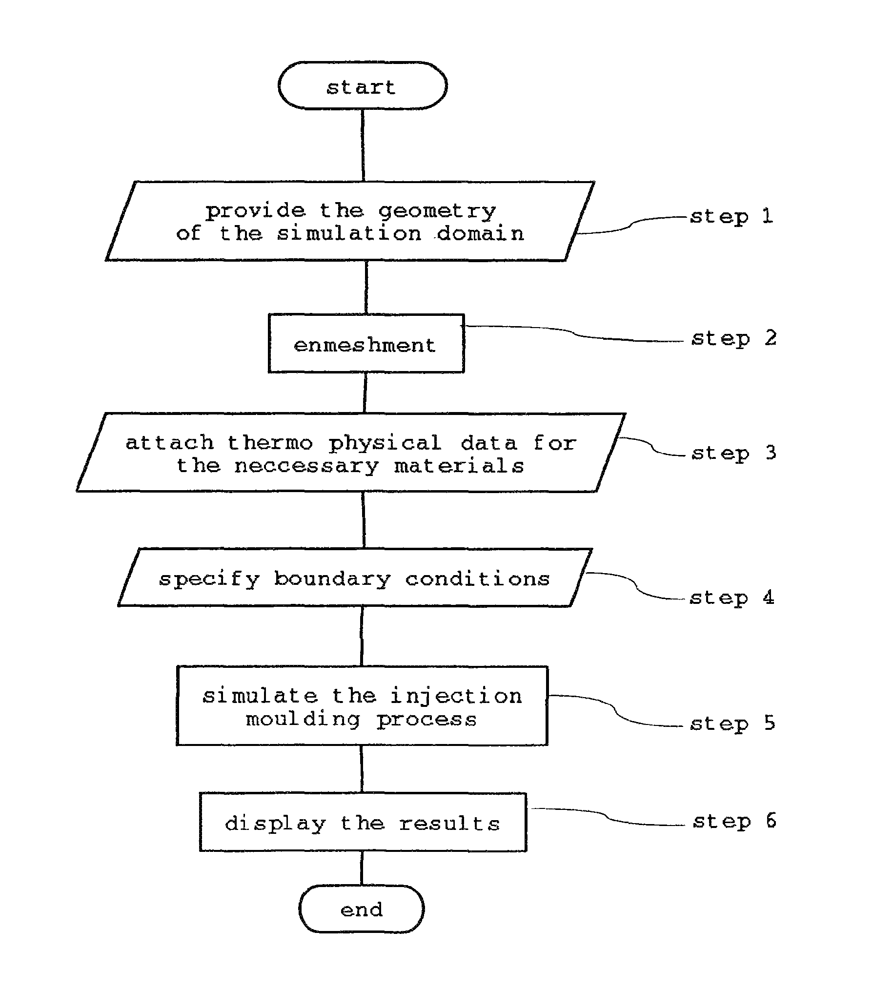
[0038]Numerical simulation of the injection moulding process on a computer can be carried out in accordance with the process illustrated in FIG. 2.

[0039]The main steps of a simulation identified generally are the following:[0040]step 1, providing a digital representation of the geometry of the simulation domain;[0041]step 2, enmeshment, which is subdivision of the calculation domain into man...


PUM

PropertyMeasurementUnit
aspect ratioaaaaaaaaaa
Daaaaaaaaaaa
sizeaaaaaaaaaa

Abstract

A method and apparatus for describing the statistical orientation distribution of nonspherical particles in a simulation of a process wherein a mold cavity is filled with a suspension that contains a large number of nonspherical particles. The method and apparatus may be applied to the analysis of an injection molding process for producing a fiber reinforced molded polymer component or of a metal casting process for producing a fiber reinforced metal product. The results of these analyses may be used to determine tension and warping aspects of the component, and to optimize the process conditions used in the production process.

Description

RELATED APPLICATIONS[0001]This application is a continuation-in-part of PCT Application PCT / EP2008 / 005361 filed Jul. 1, 2008 which claims priority from European patent application EP07012899.6 filed Jul. 2, 2007.[0002]The present invention relates to the field of three-dimensional modelling of a flow of a particle containing suspension into a mould cavity, and more specifically to a method and apparatus for describing the statistical orientation distribution of nonspherical particles in a simulation of a process wherein a mould cavity is filled with a suspension that contains a large number of nonspherical particles.BACKGROUND ART[0003]A true 3-D simulation of an injection moulding process or a metal casting process involves a system of up to several hundred thousands of equations. Progress has been made in the past to improve the efficiency of the simulation methods to cope with these complex calculations. With optimized software and the processing power of modern workstations such...

Claims


Application Information

Patent Timeline
Patent Type & Authority Patents(United States)
IPC IPC(8): G06F7/60G06F7/50G06G7/48
CPCB29C45/7693G06F17/5009B29C45/0005B29K2105/14G06F2217/41G06F2217/10B29K2105/18G06F2111/08G06F2113/22G06F30/20B29C45/76
Inventor LINN, JOACHIMMOOG, MATTHIAS
Owner MAGMA GIESSEREITECH
Learn More