Pyrolysis furnace tubes

a furnace tube and furnace technology, applied in the field of tubes, can solve the problems of increasing the rate of coke formation, thermal cracking, and the economic demands of dual-layer construction, and achieve the effects of improving mixing, improving carburization resistance, and improving mixing

Active Publication Date: 2019-07-16
EXXONMOBIL CHEM PAT INC
View PDF14 Cites 0 Cited by
  • Summary
  • Abstract
  • Description
  • Claims
  • Application Information

AI Technical Summary

Benefits of technology

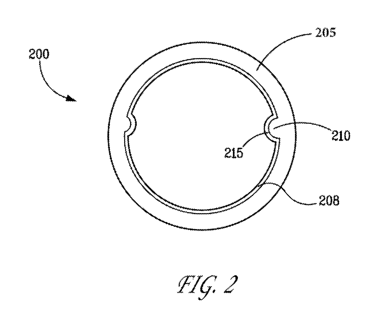
[0017]It is observed that when using the weldment of any of the preceding aspects as a radiant tube during steam cracking pyrolysis mode, a protective, carburization-resistant layer forms over at least a portion of the first tubular member's inner surface and over at least a portion of the at least one mixing element (e.g., that portion of the mixing element's surface that is exposed to steam cracking). The carburization-resistant layer comprises alumina and can be substantially free of chromium. The heat-transfer tube weldment of the invention has surprisingly improved carburization resistance compared to conventional heat-transfer tubes, while providing improved mixing associated with the presence of one or more mixing elements.
[0018]The specified heat-transfer tube weldment, thereby, provides stable, durable surfaces to resist high temperature corrosion and coking in steam cracker furnace tubes, transfer line exchangers, and other components in steam cracker plants for transporting or conveying hydrocarbon-containing process streams, which may be prone to coking.

Problems solved by technology

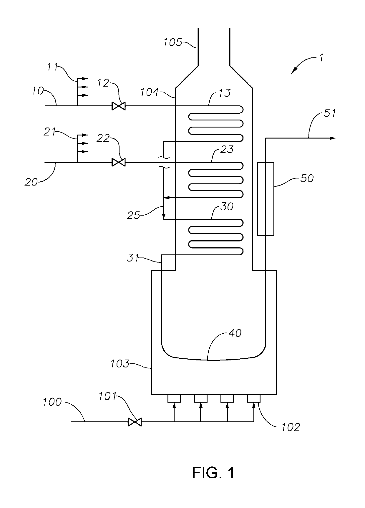
Heat transferred to the preheated hydrocarbon+steam mixture located in one or more of the radiant tubes results in thermal cracking of at least a portion of the mixture's hydrocarbon to produce a radiant coil effluent comprising molecular hydrogen, light olefin, other hydrocarbon byproducts, unreacted steam, and unreacted hydrocarbon feed.
Accordingly, discontinuities develop over time in the carburization-resistant scale located on the tube's inner surface, resulting in iron and nickel exposure to the hydrocarbon feed, leading to an increase in the rate of coke formation.
While such tubes suppress coke formation, their dual-layer construction is economically demanding.

Method used


Image

  • Pyrolysis furnace tubes
  • Pyrolysis furnace tubes

Examples


Embodiment Construction

Definitions

[0020]For the purpose of this description and appended claims, the following terms are defined. “Periodic Table” means the PERIODIC CHART OF THE ELEMENTS, The Merck Index, 12th Ed., Merck & Co., Inc., 1996.

[0021]“Steam cracker alloy” means any composition, solid solution, or solid mixture suitable for use as tubing in a steam cracking furnace for producing C2+ unsaturated hydrocarbons. Such alloys show conductivity indicating metallic behavior and include at least 10 wt. % chromium and 15 wt. % nickel, based on the weight of the steam cracker alloy.

[0022]“Weldment” means a unit formed by connecting together two or more components, where the connection includes at least one weld. The term “weldment” encompasses units formed by plasma powder welding a mixing element to a tubular member, such as a heat transfer tube suitable for use in a steam cracker. Although all components of a weldment can be joined to the weldment by welding, this is not required.

[0023]“Heat transfer tu...


PUM

PropertyMeasurementUnit
temperatureaaaaaaaaaa

Abstract

The invention relates weldments useful as heat transfer tubes in pyrolysis furnaces. The invention relates to tubes that are useful in pyrolysis furnaces. The weldments include a tubular member and at least one mixing element. The tubular member comprises an aluminum-containing alloy. The mixing element comprises an aluminum-containing alloy. The mixing element's aluminum-containing alloy can be the same as or different from the tubular member's aluminum-containing alloy. Other aspects of the invention relate to pyrolysis furnaces which include such weldments, and the use of such pyrolysis furnaces for hydrocarbon conversion processes such as steam cracking.

Description

CROSS-REFERENCE TO RELATED APPLICATIONS[0001]This application claims priority to and the benefit of U.S. Ser. No. 62 / 092,616, filed Dec. 16, 2014 and EP 15248030.7 filed Apr. 3, 2015 which are all incorporated herein by reference. This application is related to U.S. Ser. No. 62 / 199,357 filed on Jul. 31, 2015, which is also incorporated by reference.FIELD OF THE INVENTION[0002]The invention relates to tubes that are useful in pyrolysis furnaces. The tubes are weldments of a tubular member and at least one mixing element. The tubular member comprises an aluminum-containing alloy. The mixing element also comprises an aluminum-containing alloy, which can be the same as or different from the tubular member's aluminum-containing alloy. The invention also relates to pyrolysis furnaces which include such weldments, and the use of such pyrolysis furnaces for hydrocarbon conversion processes such as steam cracking.BACKGROUND OF THE INVENTION[0003]Thermal cracking of hydrocarbon feeds in the p...

Claims


Application Information

Patent Timeline
Patent Type & Authority Patents(United States)
IPC IPC(8): B01J19/24C23C30/00C23C28/00C22C38/44C22C38/48C22C38/50F16L9/02C21D9/50C10G9/36C22C19/05B23K10/02C22C30/00B23K9/04C22C38/02C22C38/04F28F1/40C10G9/14C22C38/40C10G9/20C22C19/03C10G9/16F28F21/08B01F5/06B23K101/06B23K101/20B23K103/04
CPCC10G9/203B23K9/048B23K10/027C10G9/14C10G9/16C10G9/36C21D9/50C22C19/03C22C19/05C22C30/00C22C38/02C22C38/04C22C38/40C22C38/44C22C38/48C22C38/50C23C28/345C23C30/00F16L9/02F28F1/40F28F21/08B01J19/2405C21D2211/004B01F2005/0636B23K2101/06B23K2101/20B23K2103/04B23K2103/05C22C19/058B01F25/431971
Inventor SPICER, DAVID B.CHUN, CHANGMIN
Owner EXXONMOBIL CHEM PAT INC
Why Eureka
Try Eureka