Integrated antennas and phased arrays with mode-free electromagnetic bandgap materials

a phased array and phased array technology, applied in the field of microstrip phased antenna arrays and electromagnetic bandgap materials, can solve the problems of ineffective methods and structures incorporating bandgap behavior for eliminating scan blindness and suppressing element coupling in planar phased arrays, and achieve suppression of element coupling in the substrate, suppression of scan blindness, and suppression of element coupling

Active Publication Date: 2019-08-06
RGT UNIV OF CALIFORNIA
View PDF7 Cites 2 Cited by
  • Summary
  • Abstract
  • Description
  • Claims
  • Application Information

AI Technical Summary

Benefits of technology

[0010]Existing methods and structures incorporating bandgap behavior for eliminating scan blindness and suppressing element coupling in planar phased arrays are ineffective as they degrade radiation characteristics of the antenna elements by using lossy materials or smaller radiating elements. The present invention discloses a bandgap-antenna structure capable of integrating mode-free bandgap behavior into radiating energy, when used as an antenna element. This integration suppresses element coupling in the substrate and eliminates scan blindness when used in planar phased arrays, while also removing bandgap metallization from the radiating layer. Removing said metallization effectively eliminates the antenna element size constraints presently limiting existing methods and structures. It is to be noted that the complete, four-layer structure of the present invention as a whole allows for the integration of EBG materials and antenna elements; along with geometric, size and spacing ranges of the elements comprising said structure.DEFINITIONS

Problems solved by technology

Existing methods and structures incorporating bandgap behavior for eliminating scan blindness and suppressing element coupling in planar phased arrays are ineffective as they degrade radiation characteristics of the antenna elements by using lossy materials or smaller radiating elements.

Method used


Image

  • Integrated antennas and phased arrays with mode-free electromagnetic bandgap materials
  • Integrated antennas and phased arrays with mode-free electromagnetic bandgap materials
  • Integrated antennas and phased arrays with mode-free electromagnetic bandgap materials

Examples


Embodiment Construction

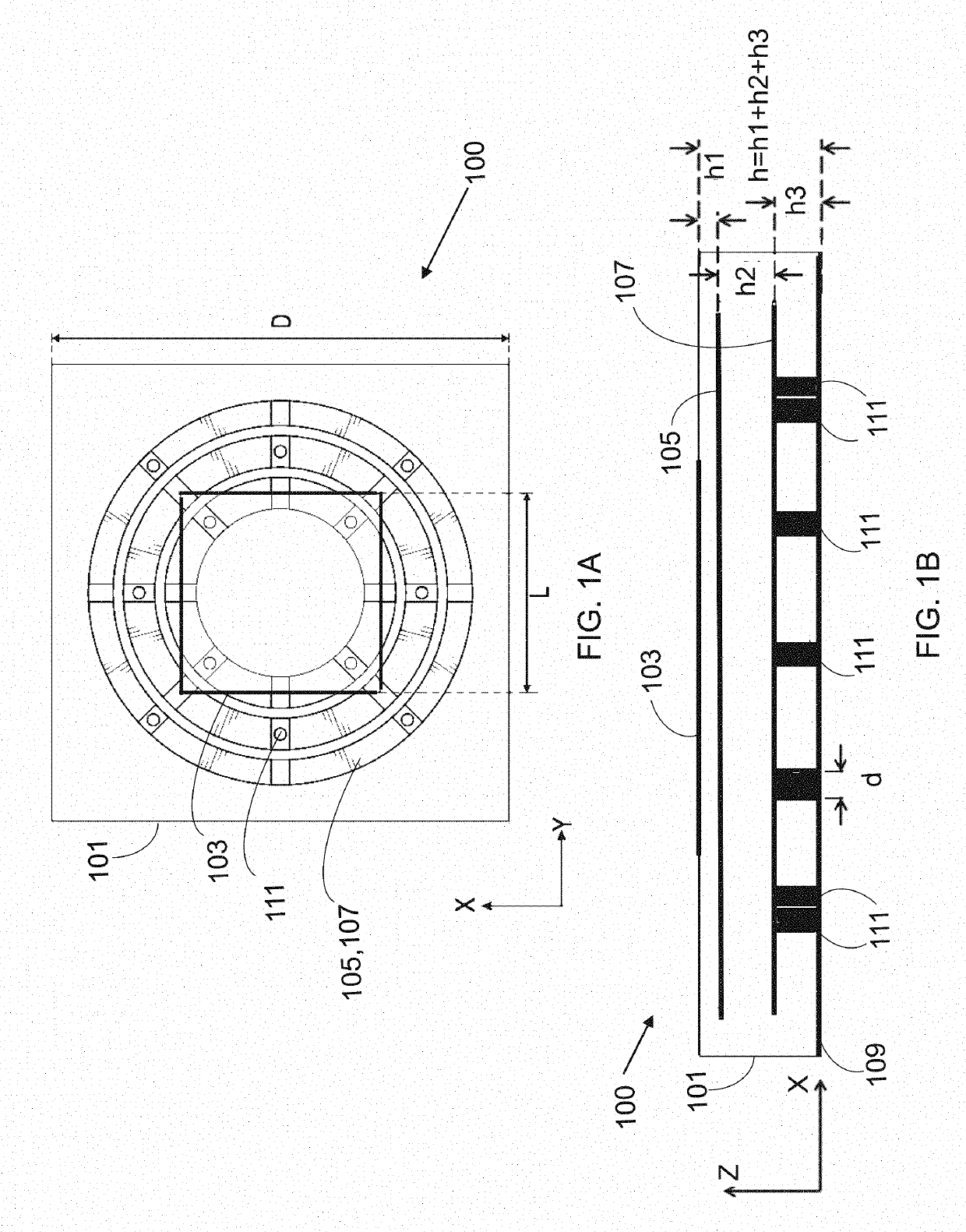
[0040]Referring now to FIGS. 1A-14, the present invention features a novel bandgap-antenna structure (100) configured to operate as an antenna element integrating mode-free omnidirectional bandgap behavior. Said integration effectively eliminates the effects of substrate waves. For example, scan blindness is eliminated when the bandgap-antenna structure is used as a phased array.

[0041]In some embodiments, the bandgap-antenna structure (100) comprises: an antenna layer (103) disposed on a top surface of a substrate (101); an upper embedded metallic layer (105) disposed within the substrate (101) below the antenna layer; a lower embedded metallic layer (107) electrically coupled to and disposed below the upper embedded metallic layer (105); and a backing ground plane (109) operatively coupled to a bottom surface of the substrate (101). The antenna layer (103), the upper and lower embedded metallic layers (105,107), and the backing ground plane (109) may be aligned such that a center o...


PUM


Abstract

A multifunctional electromagnetic structure is presently disclosed. Said structure is a true electromagnetic bandgap (“EBG”) material, with both surface and leaky waves suppressed from the whole structure along all lateral directions. It is also an antenna element, configured to radiate to the broadside direction. The structure has two metallization layers of concentric rings between a square-shaped radiating top metal layer and a bottom ground plane. The lower concentric ring is connected to the ground plane through a plurality of vias, while the patch of the top metal layer is fed with a probe. The EBG unit cells may be used as antenna elements in a phased array environment, where they eliminate scan blindness from the array structure along all scan directions.

Description

CROSS REFERENCE[0001]This application claims priority to U.S. Patent Application No. 62 / 409,283, filed Oct. 17, 2016, the specification(s) of which is / are incorporated herein in their entirety by reference.FIELD OF THE INVENTION[0002]The present invention relates to microstrip phased antenna arrays and electromagnetic bandgap materials, and more particularly, to mode-free antenna elements along the lateral directions for scan blindness-free phased arrays.BACKGROUND OF THE INVENTION[0003]The scan blindness phenomenon [1-6] is a fundamental limitation of microstrip phased arrays. Its elimination is essential to sustain communication links between wide scan angle wireless systems. Even though it is a well-known problem attributed to the coherent coupling between substrate modes and array radiation, its elimination has remained a challenge. In fact, several different approaches have been utilized to completely eliminate it or improve array scan characteristics, each of these approaches ...

Claims


Application Information

Patent Timeline
Patent Type & Authority Patents(United States)
IPC IPC(8): H01Q1/38H05K1/02H01Q21/20H01Q21/06H01Q15/14H05K1/03H01P3/08H01Q15/00H01P1/20
CPCH01P1/2005H01P3/08H01Q15/006H01Q15/008H05K1/036H01Q15/14H01Q21/065H01Q21/205H05K1/0236H01Q15/0086
Inventor ADAS, ENVERDE FLAVIIS, FRANCOALEXOPOULOS, NICOLAOS G.
Owner RGT UNIV OF CALIFORNIA
Why Eureka
Try Eureka