Polymeric ceramic precursors, apparatuses, systems, and methods
a technology of polymer ceramics and precursors, applied in the field of polymer ceramic precursors, apparatuses, systems, and methods, can solve the problems of poor toughness and certain processing conditions required for their preparation, reducing the density of articles, and products with complex shapes also can be much more difficult to achiev
- Summary
- Abstract
- Description
- Claims
- Application Information
AI Technical Summary
Benefits of technology
Problems solved by technology
Method used
Image
Examples
example 1
[0062]Different mixtures of the carbon nanotubes and the pre-ceramic polymer described above were prepared, and the densities of these mixtures were measured in different states. Specifically, variation in the density of pre-ceramic polymers from the liquid state to the cured state, and finally to a ceramic materials was observed to contribute to the shrinkage rate, which was evaluated before 3D printing of the liquid-state pre-ceramic polymer components.
[0063]Various parts were extruded having different thicknesses, lengths, and breadths as a liquid-state pre-ceramic polymer component, and then the parts were converted to a ceramic, and the resulting thicknesses, lengths, and breadths of the ceramics were measured to determine the shrinkage rates of these materials. The shrinkage of these materials is shown at Table 4.
[0064]
TABLE 4Shrinkage allowance of 2% and 16%CNT in Polysilazane by weightInitial ValuesFinal Values%Parameter(mm)(mm)ShrinkageShrinkageThickness03.0803.0000.0802.26...
example 2
, Curing, and Pyrolysis of Liquid-state Pre-ceramic Polymer Component
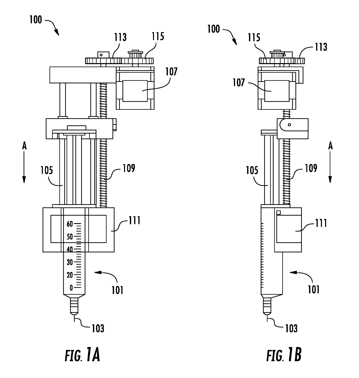
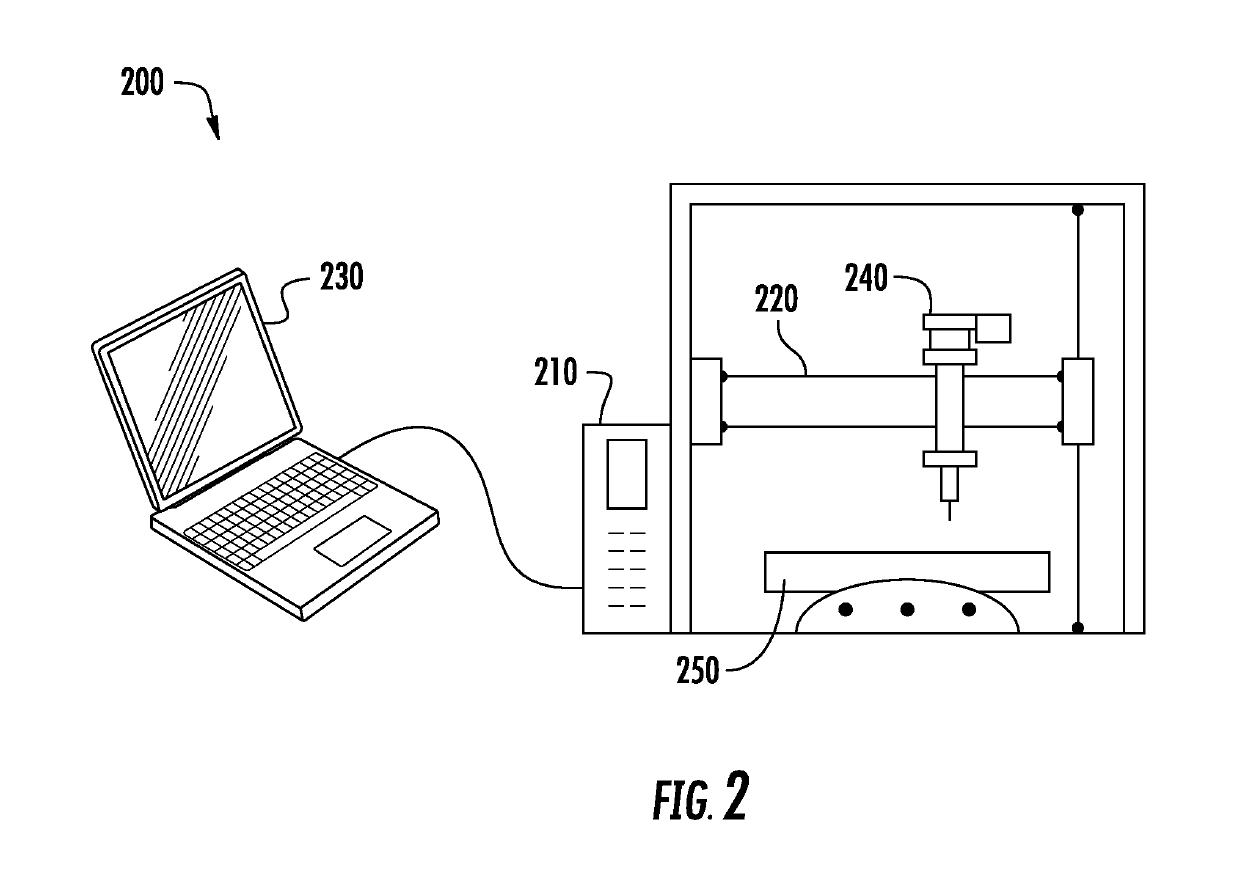
[0066]Paste samples containing 2 wt % carbon nanotubes were prepared as described at Example 1, and lowered to a temperature below the freezing point of the paste, and extruded through the 3D printer described above into various shapes. The shapes included a cube, a disc, a ring, and a square frame.
[0067]It was observed that extrusion typically occurred in three stages: (1) an initial stage, (2) a steady stage, and (3) a static stage.
[0068]In the initial stage, which lasted from the beginning of ram movement to the steady stage of paste extrusion, the paste flowed easily, but trapped gasses were seen in the syringe pump. The printed parts made during this stage were more likely to be porous than objects printed in later stages, likely due to the trapped gases.
[0069]In the steady stage, ram velocity was set above the critical value to extrude the paste, and the pressure was kept constant or nearly constant. The past...
example 3
orphology
[0073]After studying the bulk and thin materials produced at Example 2, thin layer structures were created to better evaluate the morphology of the resulting ceramic material and study its microstructure, shape, and surface texture.
[0074]A mixture of 2 wt % CNTs in polysilazane was prepared and extruded through the retrofitted 3D printer described above into the shape of a flat coil.
[0075]A visual inspection of the extrudate reavealed that it was acceptable, but some inconsistency in the structure occurred at the start of printing (the initial stage as discussed in Example 2). This inconsistency resulted in a different thickness at or near the areas where printing started. It is believed that trapped ammonia gas also may have caused or contributed to the inconsistencies.
[0076]The samples of this example were then cured at 140° C. for 24 hours, until they appeared fully cured and had a definite shape. Once the materials were fully cured, the material was observed visually. S...
PUM
| Property | Measurement | Unit |
|---|---|---|
| volume fraction | aaaaa | aaaaa |
| volume fraction | aaaaa | aaaaa |
| volume fraction | aaaaa | aaaaa |
Abstract
Description
Claims
Application Information
 - R&D
- Intellectual Property
- Life Sciences
- Materials
- Tech Scout
- Unparalleled Data Quality
- Higher Quality Content
- 60% Fewer Hallucinations
Browse by: Latest US Patents, China's latest patents, Technical Efficacy Thesaurus, Application Domain, Technology Topic, Popular Technical Reports.
© 2025 PatSnap. All rights reserved.Legal|Privacy policy|Modern Slavery Act Transparency Statement|Sitemap|About US| Contact US: help@patsnap.com


