Speculative and iterative execution of delayed data flow graphs

a data flow graph and iterative execution technology, applied in the direction of program synchronisation, program code transformation, program initiation/switching, etc., can solve the problem of reducing the affecting the execution efficiency of the execution process, and increasing the number of computation cores. problem, to achieve the effect of maximizing the flexibility of the best result selection rule and maximizing the utilization ra

Active Publication Date: 2019-08-27
COMMISSARIAT A LENERGIE ATOMIQUE ET AUX ENERGIES ALTERNATIVES
View PDF10 Cites 2 Cited by
  • Summary
  • Abstract
  • Description
  • Claims
  • Application Information

AI Technical Summary

Benefits of technology

[0036]The system according to the invention thus makes it possible to execute a data flow graph by ensuring that a result is obtained within a bounded time deterministically, while reserving the possibility of obtaining a more efficient result if it is available.
[0038]A system for executing a data flow graph according to the invention makes it possible to execute data graphs on many core processors.
[0039]A system for executing a data flow graph according to the invention makes it possible to obtain great flexibility in the best result selection rules, and to generate errors if a computation result is not obtained.
[0040]A system for executing a data flow graph according to the invention makes it possible to best exploit iterative computation algorithms. It notably makes it possible to select the best result supplied by an iterative computation algorithm on a given date, to compare this result to that produced by other iterative and non-iterative algorithms, and to terminate its execution earlier if the iterative algorithm has terminated its processing before the limit date initially planned.
[0041]A method for compiling a data flow graph according to the invention makes it possible to ensure that a result will be obtained within a bounded time deterministically.

Problems solved by technology

However, the use of additional transistors is currently caused by the increase in the number of computation cores, more than by the increase in the computation power of each of the cores.
In the context of a many core processor where the number of computation cores is particularly high, the possibility of establishing memory consistency on a large scale on all the cores is more problematical.
Without becoming impossible, its cost in terms of synchronization counterbalances the saving in execution time generated by the parallelism, the benefit of which can be compromised thereby.
It is therefore an overall unsatisfactory solution, all the more so as the memory consistency induces a not inconsiderable electrical consumption.
The Kahn model is powerful, gives deterministic results (the same inputs produce the same outputs), local (therefore without the need to have memory consistency mechanisms), but it lacks properties to be able to use it in total confidence in the context of embedded computing.
However, none of the techniques described previously makes it possible to ensure the correct execution of the data flow graph in the case of failure of one of the agents.
The risk of failure becomes not inconsiderable with the expansion of the distributed computations and of the network connections.
A connection problem, by its nature unpredictable, can then threaten the determinism of the execution, or of the time of execution, of the task performed by the agent.
Similarly, when an agent executes a task requiring external elements, for example the reception of GPS signals, it is very difficult to ensure the task execution determinism.
Furthermore, when several agents are likely to perform the same task with different result qualities, none of the abovementioned methods makes it possible to select a posteriori the one that has produced the best result.
Finally, none of the above methods makes it possible to create deterministic graphs guaranteeing the provision of a result both within a limited time and of the best possible quality out of the results supplied by several agents being running in parallel.

Method used


Image

  • Speculative and iterative execution of delayed data flow graphs
  • Speculative and iterative execution of delayed data flow graphs
  • Speculative and iterative execution of delayed data flow graphs

Examples


Embodiment Construction

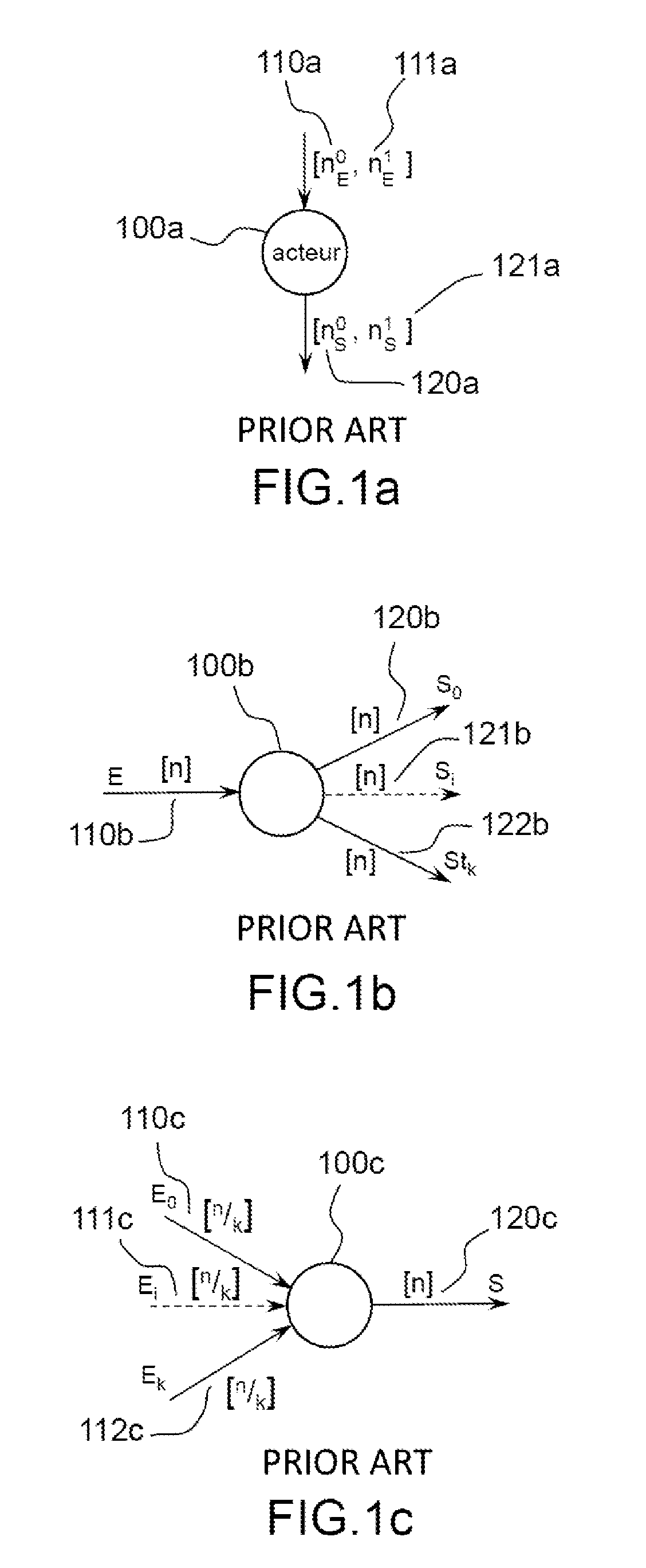
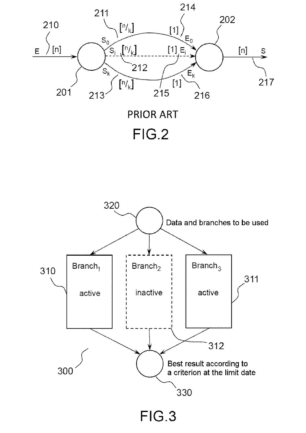
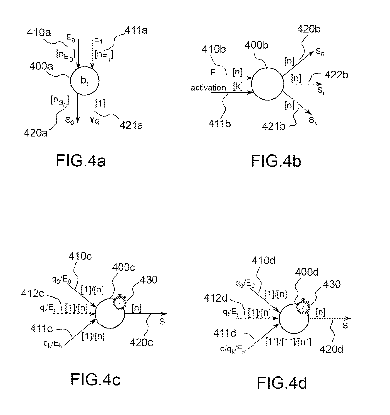
[0050]Hereinafter in the description, the implementation of the invention is illustrated by examples relating to the execution of data flow graphs of CSDF type. It should however be noted that the invention is not restricted to graphs of CSDF type. The invention is in particular applicable to the types of graphs for which it is possible to determine the latency of each branch offline, for example on compilation; for which it is possible to demonstrate the absence of deadlocks and which can be executed in bounded memory. The invention is thus applicable, for example, to the graphs of “Core Functional Dataflow” type.

[0051]Some acronyms commonly used in the technical field of the present application may be employed in the description and the figures. These acronyms are listed in the table below, with their full expression and their meaning.

[0052]

AcronymExpressionMeaningADASAdvanced DriverA driving aid computation system, forAssistance Systemexample with automatic signpostidentification...


PUM


Abstract

A system for executing a data flow graph comprises: at least two first actors each comprising means for independently executing a computation of a same data set comprising at least one datum, and producing a quality descriptor of the data set, the execution of the computation by each of at least two first actors being triggered by a synchronization system; a third actor, comprising means for triggering the execution of the computation by each of at least two first actors, and initializing a clock configured to emit an interrupt signal when a duration has elapsed; a fourth actor, comprising means for executing, at the latest at the interrupt signal from the clock: the selection, from the set of at least two first actors having produced a quality descriptor, of the one whose descriptor exhibits the most favorable value; the transfer of the data set computed by the selected actor.

Description

CROSS-REFERENCE TO RELATED APPLICATIONS[0001]This application is a National Stage of International patent application PCT / EP2015 / 071692, filed on Sep. 22, 2015, which claims priority to foreign French patent application No. FR 1458979, filed on Sep. 23, 2014, the disclosures of which are incorporated by reference in their entirety.FIELD OF THE INVENTION[0002]The present invention relates to the execution of data flow graphs with distributed computations. More specifically, it relates to the execution of data flow graphs when there is an uncertainty as to the execution of some actors of the graph.BACKGROUND[0003]Since the beginning of the new millennium, there has been a qualitative change in the progress in microprocessor and microelectronics architectures. Moore's law, which provides the roadmap for the state of the art in microelectronics etching processes continues to be borne out, since the number of transistors that can be placed on a chip still doubles approximately every 20 t...

Claims


Application Information

Patent Timeline
Patent Type & Authority Patents(United States)
IPC IPC(8): G06F9/455G06F8/40G06F13/24G06F9/52G06F11/16G06F17/50G06F11/34G06F1/10G06F15/82G06F9/48G06F8/35G06F8/41
CPCG06F9/4887G06F8/40G06F13/24G06F11/3447G06F9/4812G06F8/35G06F9/455G06F8/433G06F15/825G06F11/165G06F30/33G06F1/10G06F9/528
Inventor DUBRULLE, PAULGOUBIER, THIERRYLOUISE, STÉPHANE
Owner COMMISSARIAT A LENERGIE ATOMIQUE ET AUX ENERGIES ALTERNATIVES
Why Eureka
Try Eureka