Method and apparatus for generating electricity utilizing heat from enclosed flares and other combustors

a combustible and enclosed technology, applied in the direction of heat input, hot gas positive displacement engine plants, greenhouse gas reduction, etc., can solve the problems of large volume of heated exhaust gases, largely untapped and unutilized heat energy of said exhaust gases, and no efficient or reliable means of capturing or using said heat energy from said combustor assembly

Active Publication Date: 2019-09-17
TRISTAR TECH LLC
View PDF7 Cites 0 Cited by
  • Summary
  • Abstract
  • Description
  • Claims
  • Application Information

AI Technical Summary

Problems solved by technology

Such conventional combustor assemblies are particularly effective at burning toxic gases; however, the combustion process inevitably results in relatively large volumes of heated exhaust gases that must be released through ventilation or exhaust stacks.
In such cases, the heat energy of said exhaust gases remains largely untapped and unused.
Further, there is currently no efficient or reliable means for capturing or using said heat energy from said combustor assemblies in order to generate electricity or any other beneficial source of power.

Method used


Image

  • Method and apparatus for generating electricity utilizing heat from enclosed flares and other combustors
  • Method and apparatus for generating electricity utilizing heat from enclosed flares and other combustors
  • Method and apparatus for generating electricity utilizing heat from enclosed flares and other combustors

Examples


Embodiment Construction

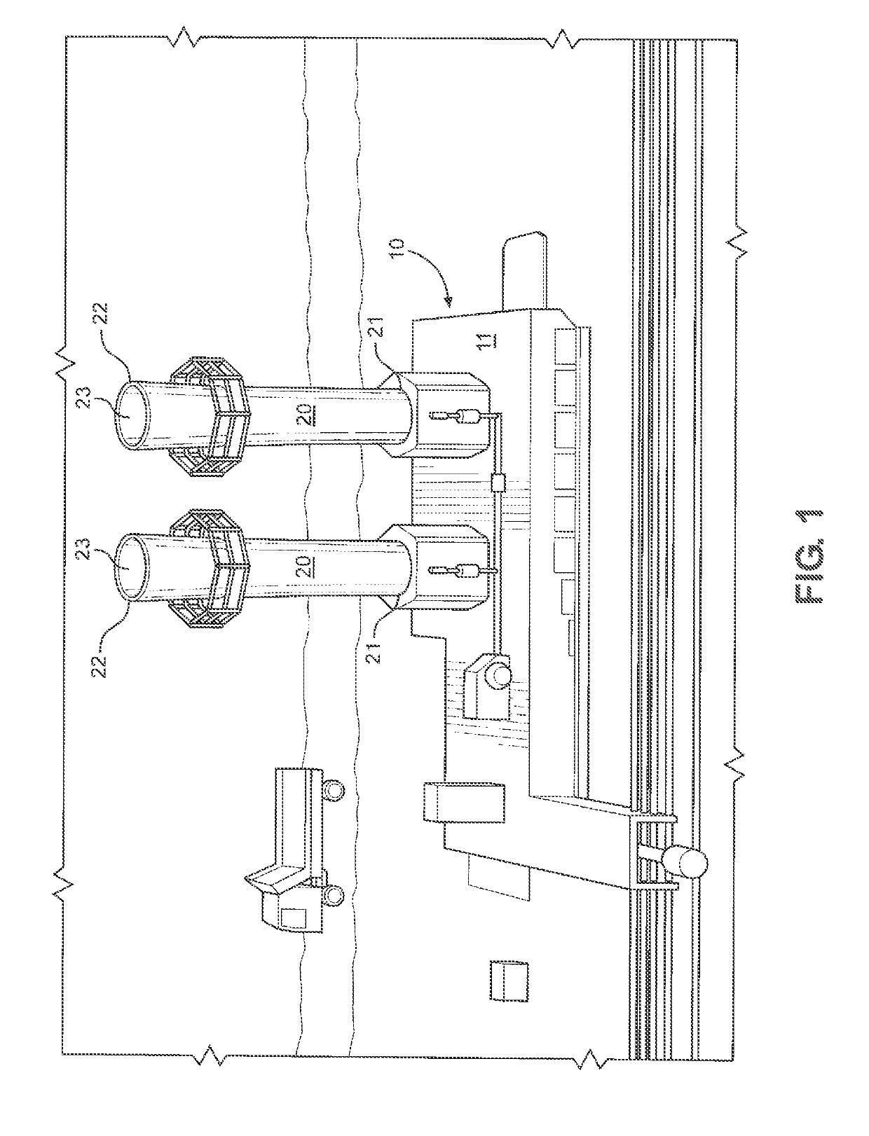
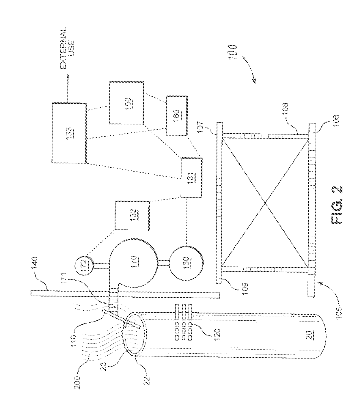
[0022]FIG. 1 depicts an overhead perspective view of a conventional combustor assembly 10. In the embodiment depicted in FIG. 1, said conventional combustor assembly 10 reflects a representative combustor design, such as commonly installed and used at oil tanker and oil barge transshipment terminals. However, it is to be observed that combustor assembly 10 could embody any number of alternative designs that could be used in many different applications without departing from the scope of the present invention.

[0023]Still referring to FIG. 1, conventional combustor assembly 10 comprises at least one combustion chamber apparatus 21, wherein gases to be burned are consumed in the combustion process. Typically, said at least one combustion chamber apparatus 21 receives hydrocarbon gases and utilizes intense heat (1,650 degrees Fahrenheit or more) to burn off said toxic hydrocarbon gases. In some cases, natural gas or other fuel is supplied to said combustion chamber apparatus 21 in order...


PUM


Abstract

A system for electricity generation using heat contained in exhaust gas from a combustor (enclosed flare) to drive an external combustion Stirling cycle engine which directly drives at least one alternator or generator. A battery is connected to the alternator or generator through a divider circuit followed by a filter circuit. Electric power distribution circuits are electrically connected to output circuits of the alternators or generators for consumption of the electric power on-site, for sale to a commercial electric power distribution grid, or for any other desired uses.

Description

CROSS REFERENCES TO RELATED APPLICATION[0001]This application claims priority of U.S. Provisional Patent Application Ser. No. 62 / 565,537, filed Sep. 29, 2017, incorporated herein by reference.STATEMENTS AS TO THE RIGHTS TO THE INVENTION MADE UNDER FEDERALLY SPONSORED RESEARCH AND DEVELOPMENT[0002]NoneBACKGROUND OF THE PRESENT INVENTION1. Field of the Invention[0003]The present invention pertains to an electric power generation system. More particularly, the present invention pertains to a method and apparatus for generating electricity utilizing heat produced from the burning of hydrocarbons or “waste gas” in combustors.2. Description of Related Art[0004]Conventional combustion assemblies—also commonly referred to as “combustors” or “enclosed flares”—are well known in the art. Such conventional combustor systems are used in a wide variety of applications and are generally used to burn off excess gas, usually hydrocarbons. Conventional combustors are generally distinguishable from op...

Claims


Application Information

Patent Timeline
Patent Type & Authority Patents(United States)
IPC IPC(8): F02G1/043F02G1/053F02G1/055
CPCF02G1/055F02G1/043F02G1/053F02G2254/15F02G2280/20F02G2255/00Y02E20/30
Inventor NUNN, JAMES W.
Owner TRISTAR TECH LLC
Why Eureka
Try Eureka