Optical communications system phase-controlled transmitter and phase-conjugate mirror receiver

a technology of optical communication system and transmitter, which is applied in the field of optical communication system phase-controlled transmitter and phase-conjugate mirror receiver, can solve the problems of information loss and inability to confirm connection, and achieve the effects of small physical footprint, low power consumption, and robust handshaking

Active Publication Date: 2019-09-17
CHARLES STARK DRAPER LABORATORY
View PDF8 Cites 3 Cited by
  • Summary
  • Abstract
  • Description
  • Claims
  • Application Information

AI Technical Summary

Benefits of technology

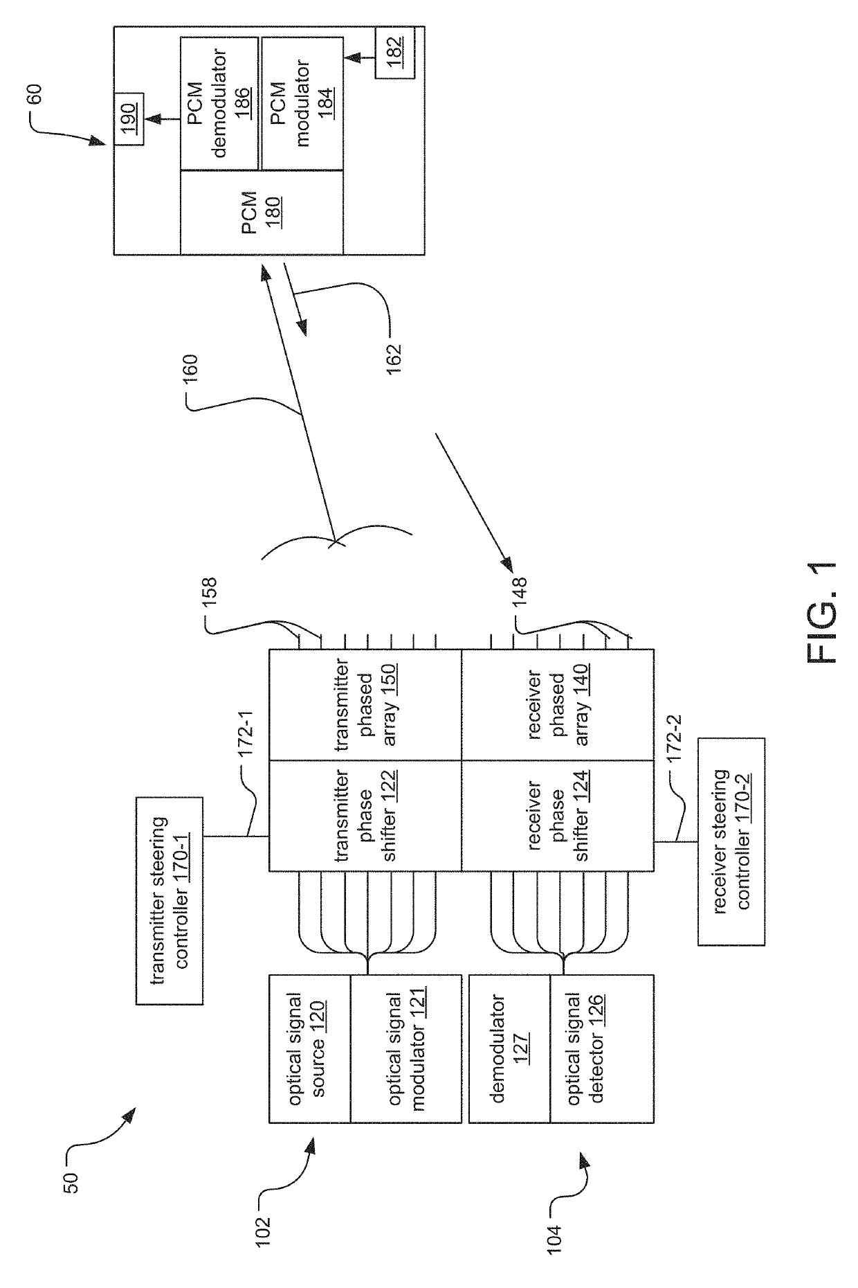
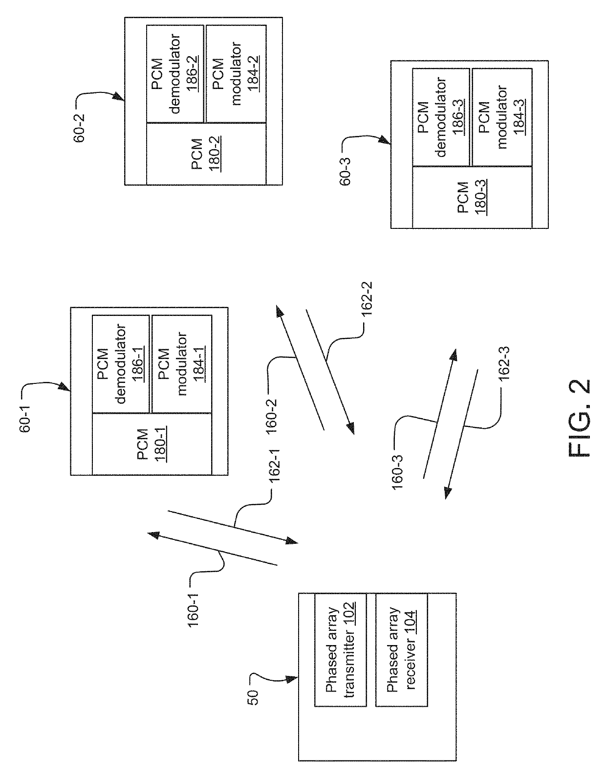
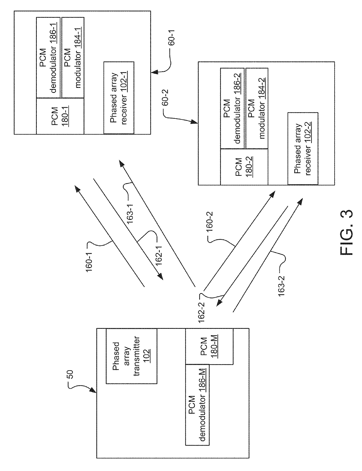
[0007]The present invention uses phased array transmitters and phase conjugate mirrors to complete the optical communications links. The phased array transmitters allow for electronic steering of the beams in a way that is much faster and with a potentially smaller physical footprint than mechanical systems. The phase conjugate mirrors return the received beams of photons back over the exact path they were sent from the phased array transmitters, ensuring continuity of communication even in the presence of atmospheric turbulence.
[0008]This solution can provide robust handshaking between the transmitter and the receiver. It can also account for link disturbances due to such effects as atmospheric disturbance and eliminates the need for mechanically steering either the transmitter or receiver.
[0009]The phase controlled light source and the phase conjugate mirror can be small and use very little power. These characteristics are critical for mobile applications. This small size and low power requirement make it possible to use this architecture in numerous applications.
[0010]A number of advantages can be obtained when employing the invention. For example, the implemented system can have a small form factor: The solid state nature of the phase controlled transmitter and phase conjugate minors enable extremely small transmitters and receivers. This enables free-space communications between mobile nodes including cell phones and other small devices. Further, power consumption can be lower. The beam is steered electronically and the phase controlled transmitter directs the light directly at the mirror. The phase conjugate mirror reflects the light straight back down the transmit channel, so there is little or no loss on the return trip. Thus, only a small amount of light is required to maintain handshaking between the transmitter and receiver. Finally, solid state steering of the transmit beam and phase conjugate reflection of the mirror enable high speed steering of the communications channel without the need for mechanical steering systems that are extremely slow in comparison. This will be a completely solid state communications and position tracking system. This allows two platforms to move relative to each other at a rather rapid rate while still maintaining communications. For example, this would enable a cell communications architecture in a light based communication medium. In addition, relative position (range, elevation, azimuth) and velocity can be determined, enabling a host of applications not possible with a straight forward communications channel implementation.

Problems solved by technology

Moreover, mechanically steered systems are large, making it difficult to have a laser optical transmitter and receiver at each end if handshaking is desired to enable error handling and correction; and without this feedback mechanism, connectivity cannot be confirmed and information can be lost if the optical communication link drops out.

Method used


Image

  • Optical communications system phase-controlled transmitter and phase-conjugate mirror receiver
  • Optical communications system phase-controlled transmitter and phase-conjugate mirror receiver
  • Optical communications system phase-controlled transmitter and phase-conjugate mirror receiver

Examples


Embodiment Construction

[0028]The invention now will be described more fully hereinafter with reference to the accompanying drawings, in which illustrative embodiments of the invention are shown. This invention may, however, be embodied in many different forms and should not be construed as limited to the embodiments set forth herein; rather, these embodiments are provided so that this disclosure will be thorough and complete, and will fully convey the scope of the invention to those skilled in the art.

[0029]As used herein, the term “and / or” includes any and all combinations of one or more of the associated listed items. Further, the singular forms and the articles “a”, “an” and “the” are intended to include the plural forms as well, unless expressly stated otherwise. It will be further understood that the terms: includes, comprises, including and / or comprising, when used in this specification, specify the presence of stated features, integers, steps, operations, elements, and / or components, but do not pre...


PUM


Abstract

An optical communications system comprises a first node comprising a phased array transmitter for generating an optical beam and a receiver, and a second node comprising a phase conjugate mirror for returning the optical beam to be detected by the receiver of the first node. The phased array transmitters allow for electronic steering of the beams in a way that is much faster and with a potentially smaller physical footprint than the mechanical systems. The phase conjugate mirrors return the received beams of photons back over the exact path they were sent from the phased array transmitters, ensuring continuity of communication even in the presence of atmospheric turbulence.

Description

RELATED APPLICATIONS[0001]This application claims the benefit under 35 USC 119(e) of U.S. Provisional Application No. 62 / 340,582, filed on May 24, 2016, which is incorporated herein by reference in its entirety.BACKGROUND OF THE INVENTION[0002]As a general rule, free-space optical communication systems have a number of advantages over other communication systems. They offer a level of security that is not present in a radiofrequency system; the optical communication signal beam can be highly collimated and directed at the intended optical receiver. In addition, optical communication links can transmit at very high data rates.[0003]Former methods to produce such free-space optical communications systems involved the use of multiple optical receivers and high powered, mechanically steered laser optical transmitters. Since the laser beam could not be electronically steered, its direction was controlled by a mechanical gimbal system, for example. The receivers of the optical communicati...

Claims


Application Information

Patent Timeline
Patent Type & Authority Patents(United States)
IPC IPC(8): H04J14/08H04B10/112H04B10/071H04B7/185H01Q3/26
CPCH04B10/071H01Q3/2676H04B10/1129H04B7/18504H04B10/1123H04J14/08
Inventor DAWSON, ROBIN MARK ADRIANLAINE, JUHA PEKKASPECTOR, STEVENCHAPARALA, MURALI
Owner CHARLES STARK DRAPER LABORATORY
Why Eureka
Try Eureka