Steel plate alkali electrolyzer

a technology of alkali electrolyzer and steel plate, which is applied in the direction of combustion air/fuel air treatment, machines/engines, mechanical equipment, etc., can solve the problems of significantly affecting pm reduction and fuel efficiency, and exceeds the efficiency of all other known electrolyzer designs, and achieves less complex and less expensive construction.

Active Publication Date: 2019-09-24
WARNER STANLEY WESLEY
View PDF2 Cites 2 Cited by
  • Summary
  • Abstract
  • Description
  • Claims
  • Application Information

AI Technical Summary

Benefits of technology

[0002]This improved steel plate alkali electrolyzer comprises steel plates wrapped by an insulating material holding the plates in precise spacing without the use of gaskets. The plates and the insulating material are surrounded by a containment vessel that is filled with electrolyte. The plates are designed so that the anode and cathode plates are longer that the other bi-polar plates and extend outside of the containment vessel so there is no electrical connection inside the containment vessel. The number of steel plates used is determined by formula to most efficiently affect the electrolysis process. The shape of the plates leads to more efficient electrolysis by not having holes in the area of the plates that produce electrolysis that would allow the electricity to pass through the holes and not create hydrogen, along with having an insulating material hold the plates in precise alignment and not allowing electricity to move around the edges of the plates but force the electricity to pass through the plates creating more Brown's gas. The shape of the plates also adds to the circulating of the electrolyte. The circulation of the electrolyte is caused by the warmer electrolyte rising in the electrolyzer and the bubbles from the Brown's gas adding to the speed and volume of that process. The warmer electrolyte and the Brown's gas bubbles exit the containment vessel at the top of the containment vessel. The Brown's gas goes to the point of use and the electrolyte is cooled by being outside of the containment vessel and then the cooler electrolyte reenters the containment vessel at the bottom further keeping the electrolyte and plates cooler and more efficient in the production of Brown's gas, than they would otherwise be without the recirculating liquid. This recirculation is accomplished without a pump or other mechanical means. This efficient and inexpensive design is scalable and exceeds in efficiency all other known electrolyzer designs for on-board production for internal combustions engines and for hydrogen production for hydrogen fuel cell vehicles.
[0004]The design of this improved steel plate alkali electrolyzer is less complicated and less expensive to construct than other electrolyzers. This advantage is further added to the fact that this design is scalable, it can be produced to create small, mid-range or large amounts of Brown's gas. This is a great advantage allows for the great efficiency of this unit to fit several Brown's gas and hydrogen commercial needs from a competitively advantageous position.

Problems solved by technology

The shape of the plates leads to more efficient electrolysis by not having holes in the area of the plates that produce electrolysis that would allow the electricity to pass through the holes and not create hydrogen, along with having an insulating material hold the plates in precise alignment and not allowing electricity to move around the edges of the plates but force the electricity to pass through the plates creating more Brown's gas.
This efficient and inexpensive design is scalable and exceeds in efficiency all other known electrolyzer designs for on-board production for internal combustions engines and for hydrogen production for hydrogen fuel cell vehicles.
The present art of a steel plate alkali electrolyzer is that they are too inefficient for on-board production of Brown's gas for internal combustion engines to significantly affect PM reduction and fuel efficiency.

Method used


Image

  • Steel plate alkali electrolyzer
  • Steel plate alkali electrolyzer
  • Steel plate alkali electrolyzer

Examples


Embodiment Construction

[0010]Embodiment of the present invention overcome many of the obstacles associated with efficient electrolysis and now will be described more fully hereinafter with reference to the accompanying drawings that show some, but not all embodiments of the claimed inventions. Indeed, the invention may be embodied in many different forms and should not be construed as limited to the embodiments set forth herein. Rather, these embodiments are provided so that this disclosure will satisfy applicable legal requirements. Like numbers refer to like elements throughout.

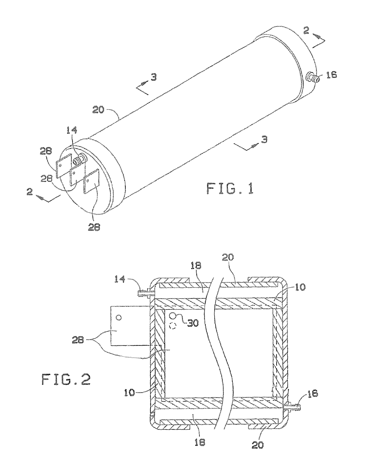
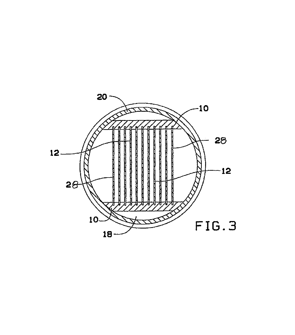
[0011]FIG. 1 shows the improved steel plate alkali electrolyzer. The improved electrolyzer comprises, containment vessel 20 which is shown in more detail in FIG. 2 and FIG. 3.

[0012]The anode and cathode plates that extend outside of the containment vessel 28 are shown in FIG. 1, FIG. 2 and FIG. 3.

[0013]FIG. 1 shows the exit location of Brown's gas and warmer electrolyte 14 and the recirculation inlet where the cooler electrolyte ...


PUM

PropertyMeasurementUnit
lengthaaaaaaaaaa
heightaaaaaaaaaa
widthaaaaaaaaaa

Abstract

An improved steel plate alkali electrolyzer uses an anode steel plate, by-polar steel plates, and a cathode steel plate (the number of bi-polar plated is determined by the voltage applied, the formula explained in Claim). The steel plate edges are wrapped with an insulating material to hold them in precise alignment. This unit is housed in a containment vessel, with the anode and cathode steel plates extending past the outside of the containment vessel to make electrical connections outside of liquid filled vessel. Shape and arrangement of the plates enables the gas production to create a circulating electrolyte (without the use of a pump) that produces a cooler operating and more efficient production of Brown's gas per watt, and less expensive to construction than any other known electrolyzer. Design is scalable allowing for a wide range of gas production and applications.

Description

(1) BACKGROUND OF THE INVENTION[0001]This invention teaches a significant advancement in Brown's gas production efficiency increase above the current production efficiently levels of the present art of steel plate alkali electrolyzers. This new efficiency in this steel plate alkali electrolyzer will have a profound effect on the following—The benefit of infusing Brown's gas in internal combustion engines, especially diesels, is well known. Lesser known is the fact that particulate matter (PM) poisoning from diesel engines, just in California, is the cause of death of about 10 people per day. The infusion of Brown's gas into diesel engines can drastically reduce the PM that that causes those 10 fatalities per day in California alone. It is also well known that present electrolyzers are too inefficient to be used for on-board production for internal combustion engines (the presently available electrolyzers use too much electricity to generate the needed amounts of Brown's gas to cause...

Claims


Application Information

Patent Timeline
Patent Type & Authority Patents(United States)
IPC IPC(8): C25D17/02C25B15/02C25B1/04C25D17/08F02M27/04C25B9/06C25B9/17
CPCF02M27/04C25B1/04C25B15/02C25B9/06C25B11/03F02M25/12Y02E60/36Y02T10/12C25B11/036C25B9/17
Inventor WARNER, STANLEY WESLEY
Owner WARNER STANLEY WESLEY
Why Eureka
Try Eureka