
Manufacturing methods for magnetic core inductors with biased permeability

a technology of magnetic core and inductors, which is applied in the field of manufacturing methods of magnetic core inductors with biased permeability, can solve the problems of increasing bulky and heavy for high-current equipment, limited methods, and low efficiency

Active Publication Date: 2019-10-01
FERRIC INC
View PDF44 Cites 0 Cited by
  • Summary
  • Abstract
  • Description
  • Claims
  • Application Information

AI Technical Summary

Benefits of technology

The present invention is about new methods and devices for creating on-chip inductive elements with magnetic cores. These devices use biasing coils to control the permeability of the magnetic core and can be used in microelectronic applications. An electrical current through the bias coils generates magnetic fields that align the magnetic materials in the core, resulting in a desirable orientation of anisotropy. This enables the modulation of the inductive response of the device. Overall, this technology provides improved performance and control over inductive elements, making them more efficient and reliable in microelectronic applications.

Problems solved by technology

However, these methods are limited and other approaches are necessary to increase device density, processing power and to reduce power consumption and heat generation in the same.
Conventional AC-AC and AC-DC power supplies are usually a relatively simple design, but they become increasingly bulky and heavy for high-current equipment.
Conventional DC-DC converter, linear voltage regulators, produce regulated output voltage by means of an active voltage divider that consumes energy, thus making efficiency low.
The switching duty cycle increases as power output requirements increase which puts increasing demands on the constituent components, particularly the inductors.
This adds to the circuit complexity, with the inclusion of additional inductors and capacitors.
Additionally, the delivery of low voltage / high current power is also challenging because power loss increases with higher currents, as follows:
Unfortunately, practical integrated inductors that are capable of efficiently carrying large current levels for switched-inductor power conversion are not available.
However, high permeability materials tend to saturate when biased by a large direct current (DC) magnetic field.
Magnetic saturation can have adverse effects as it results in reduced permeability and consequently reduced inductance.
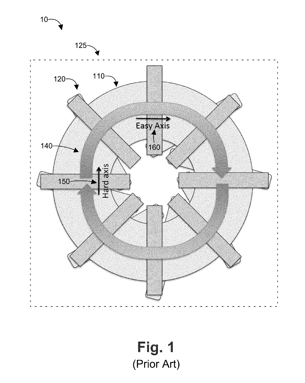
This is undesirable because the easy axis 160 of the core has a greater coercivity (and thus non-linearity), which results in magnetic saturation as discussed above.

Method used


Image

  • Manufacturing methods for magnetic core inductors with biased permeability
  • Manufacturing methods for magnetic core inductors with biased permeability
  • Manufacturing methods for magnetic core inductors with biased permeability

Examples


Embodiment Construction

[0050]As mentioned above, the present invention relates to inductive elements that utilize anisotropic materials and incorporate secondary biasing coils for the purpose of biasing the magnetic cores. One or more embodiments or implementations are hereinafter described in conjunction with the drawings, where like reference numerals are used to refer to like elements throughout, and where the various features are not necessarily drawn to scale.

[0051]The present invention discloses a novel inductor which can be integrated into large scale chip fabrication, according to one embodiment. Inductance is the property of a conductor by which a change in current in the conductor “induces” (creates) a voltage (electromotive force) in both the conductor itself (self-inductance) and in any nearby conductors (mutual inductance). These effects are derived from two fundamental observations of physics: first, that a steady current creates a steady magnetic field (Oersted's law), and second, that a ti...


PUM

PropertyMeasurementUnit
temperatureaaaaaaaaaa
DC voltagesaaaaaaaaaa

Abstract

A method of forming an inductor assembly includes depositing a magnetic core on a planar substrate lying in a core plane, forming an inductor coil that generates a magnetic field that passes through the magnetic core in a closed loop parallel to the core plane, and annealing the magnetic core while applying an external magnetic field that passes through the magnetic core in a radial direction to permanently fix the easy axis of magnetization parallel to the radial direction. As a result, the hard axis of magnetization of the magnetic core is permanently oriented in a generally circular closed path parallel to the closed loop of the inductor's magnetic field.

Description

CROSS REFERENCE TO RELATED APPLICATIONS[0001]This application is a continuation of and claims priority to U.S. patent application Ser. No. 14 / 746,994, entitled “Apparatus and Methods for Magnetic Core Inductors with Biased Permeability,” filed on Jun. 23, 2015, now U.S. Pat. No. 9,991,040, which claims priority to U.S. Provisional Application No. 62 / 015,726, entitled “Apparatus and Methods for Magnetic Core Inductors with Biased Permeability,” filed on Jun. 23, 2014, which is hereby incorporated herein by reference.TECHNICAL FIELD[0002]The present application is directed to inductive elements comprising anisotropic media, means for magnetically biasing thereof and methods of manufacture and operation for use in applications such as microelectronics.BACKGROUND[0003]The increase in computing power, spatial densities in semiconductor based devices and energy efficiency of the same allow for ever more efficient and small microelectronic sensors, processors and other machines. These have...

Claims


Application Information

Patent Timeline
Patent Type & Authority Patents(United States)
IPC IPC(8): H01F27/24H01F41/14H01L49/02H01F41/04H01F41/06H01F1/147H01F13/00H01F17/00H01F17/04H01F17/06H01F27/255H01F27/38H01F27/28C23C14/14H01F10/12H10N97/00
CPCH01F13/003H01F17/04H01F17/0013H01F27/24H01F41/14H01F27/2823H01F27/38H01L28/10H01F17/062H01F27/255H01F41/06H01F1/14708H01F41/046Y10T29/49075H01F27/2895Y10T29/49073H01F10/12H01F2017/0066C23C14/14
Inventor STURCKEN, NOAHDAVIES, RYANWU
Owner FERRIC INC
Learn More