Method of subatmospheric plasma-enhanced ALD using capacitively coupled electrodes with narrow gap

a capacitively coupled electrode and subatmospheric technology, applied in the direction of chemical vapor deposition coating, electric discharge tubes, coatings, etc., can solve the problems of inferior film properties such as chemical resistance and dry etching resistance of a film deposited on a sidewall of a fine trench, and achieve the effect of improving the conformality of a deposited carbon-based film and poor conformality

Active Publication Date: 2019-10-08
ASM IP HLDG BV
View PDF2885 Cites 251 Cited by
  • Summary
  • Abstract
  • Description
  • Claims
  • Application Information

AI Technical Summary

Benefits of technology

[0004]In some embodiments of the present invention, thermal plasma is generated by PEALD at subatmospheric pressure using a conventional or any suitable capacitively coupled plasma (CCP) apparatus wherein process pressure is significantly increased and the gap between two parallel plate electrodes is significantly narrowed to 5 mm or less. In some embodiments, silicon-based insulation films or metal-based insulation films can effectively be deposited using subatmospheric PEALD, wherein properties of a film deposited at the sidewall of a trench or other patterned recess are remarkably improved, and, for example, surprisingly, wet etch rate (WER) of the sidewall film can be rendered approximately the same as that of top (blanket) film. In some embodiments, a carbon-based film which normally shows poor conformality due to insufficient ion bombardment at the sidewall even using an ALD mode can be deposited by subatmospheric PEALD, wherein the conformality of a deposited carbon-based film can significantly be improved.

Problems solved by technology

However, as device miniaturization progresses, PEALD faces a problem that film properties such as chemical resistance and dry etching resistance of a film deposited on a sidewall of a fine trench are inferior to those of a film deposited on a flat surface due to uneven ion bombardment by a plasma where ion bombardment is weaker at the sidewall than that on the flat surface.

Method used


Image

  • Method of subatmospheric plasma-enhanced ALD using capacitively coupled electrodes with narrow gap
  • Method of subatmospheric plasma-enhanced ALD using capacitively coupled electrodes with narrow gap
  • Method of subatmospheric plasma-enhanced ALD using capacitively coupled electrodes with narrow gap

Examples


examples 1 to 7

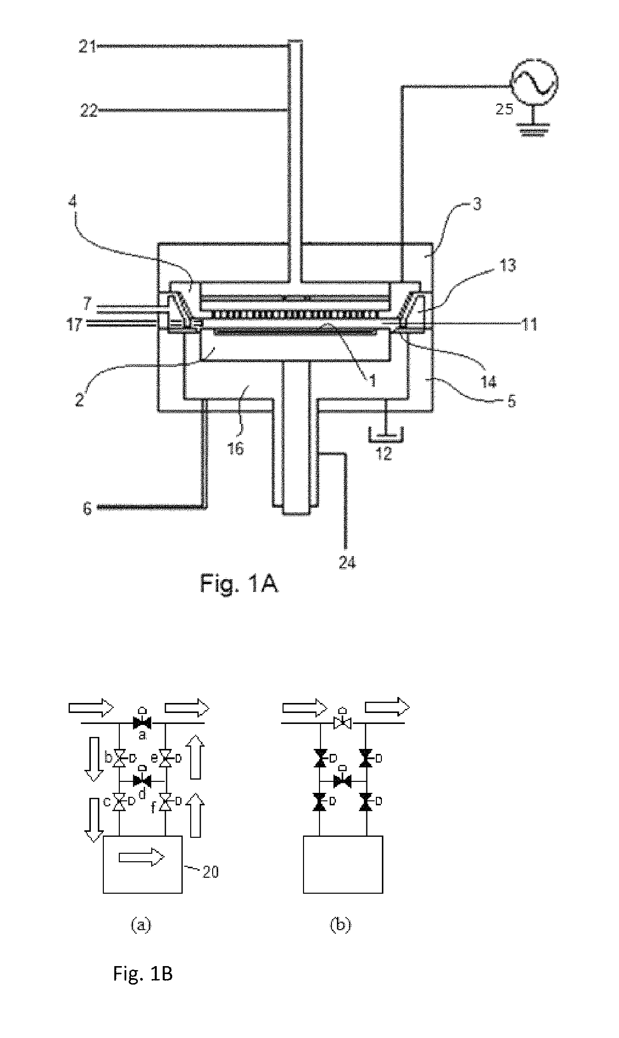
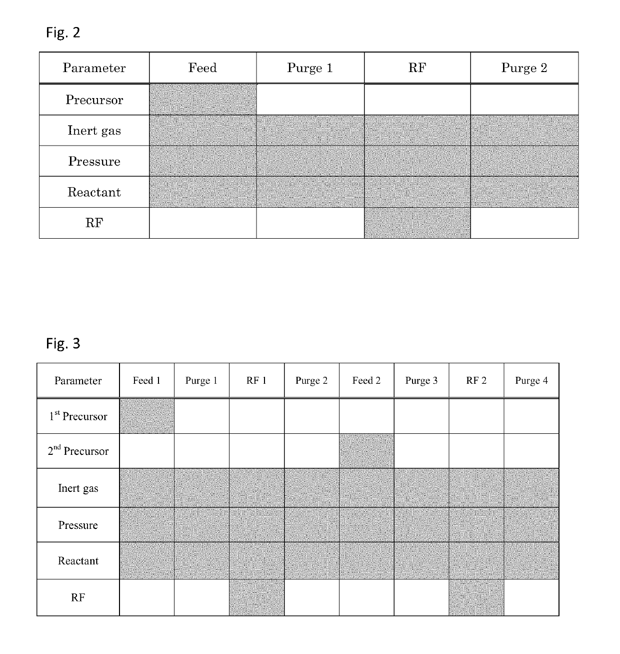
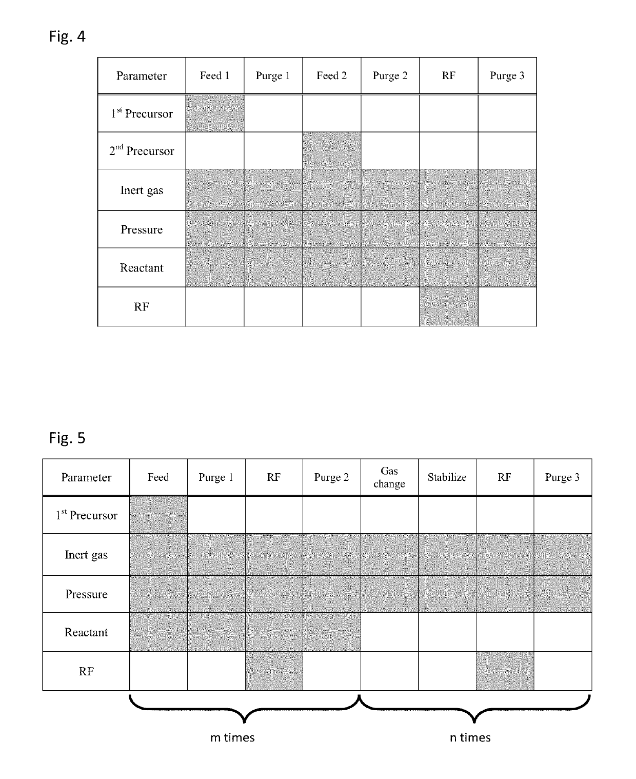
[0068]A film was formed on a Si substrate (having a diameter of 300 mm and a thickness of 0.7 mm) having trenches with an aspect ratio of 4 (a width of 25 nm, and a depth of 100 nm) by subatmospheric PEALD using a sequence illustrated in FIG. 2, one cycle of which was conducted under the common conditions shown in Table 3 (process cycle) below using the PEALD apparatus illustrated in FIG. 1A and a gas supply system (FPS) illustrated in FIG. 1B with the specific conditions and sequence indicated in Table 4.

[0069]

TABLE 3(numbers are approximate)Common Conditions for Process CycleCarrier gas and dilution gasArFlow rate of carrier gas (continuous)2 slmPrecursor pulse1 secPurge after precursor feed pulse2 secRF power pulse1 secPurge after RF power pulse1 sec

[0070]

TABLE 4(numbers are approximate)Dilu-Temp.PressureRFGapReactant / tionPrecursor(° C.)(kPa)(W)(mm)slm(slm)*1Bisdimethyl-3000.410012O2 / 0.11aminosilane*2Dichlorotetra-4000.420012NH3 / 21mehyldisilane*3Divinyldimethyl-3000.410012CO2 / 0.1...


PUM

PropertyMeasurementUnit
distanceaaaaaaaaaa
pressureaaaaaaaaaa
pressureaaaaaaaaaa

Abstract

A method for depositing a film by plasma-enhanced subatmospheric-pressure atomic layer deposition (subatmospheric PEALD) is conducted using capacitively coupled parallel plate electrodes with a gap of 1 mm to 5 mm, wherein one cycle of subatmospheric PEALD includes: supplying a precursor in a pulse to the reaction chamber; continuously supplying a reactant to the reaction chamber; continuously supplying an inert gas to the reaction chamber; continuously controlling a pressure of the reaction chamber in a range of 15 kPa to 80 kPa; and applying RF power for glow discharge in a pulse to one of the parallel plate electrodes.

Description

BACKGROUND OF THE INVENTIONField of the Invention[0001]The present invention generally relates to a method of plasma-enhanced atomic layer deposition (PEALD), particularly a method of subatmospheric PEALD using capacitively coupled electrodes with a narrow gap.Description of the Related Art[0002]Conventionally, in plasma-enhanced atomic layer deposition (PEALD), a plasma is generated in between two parallel plate electrodes that are spaced about 1 to 5 cm apart, from a source gas at low pressure (1 to 10 mTorr) (Stephan Heil, “Plasma-Assisted Atomic Layer Deposition of Metal Oxides and Nitrides”, Technische Universiteit Eindhoven, 2007, p. 6). Since PEALD uses a self-limiting adsorption reaction process, conformality of a thin film deposited by PEALD is high. However, as device miniaturization progresses, PEALD faces a problem that film properties such as chemical resistance and dry etching resistance of a film deposited on a sidewall of a fine trench are inferior to those of a film...

Claims


Application Information

Patent Timeline
Patent Type & Authority Patents(United States)
IPC IPC(8): C23C16/505C23C16/34C23C16/32C23C16/509C23C16/40C23C16/44C23C16/455C23C16/52C23C16/04
CPCC23C16/509C23C16/52C23C16/045C23C16/505C23C16/45527C23C16/45542C23C16/40C23C16/32C23C16/401C23C16/345C23C16/325C23C16/34C23C16/4412C23C16/45536C23C16/513H01J37/32834H01J37/32449H01J37/32816H01J37/3299C23C16/45544C23C16/24C23C16/06C23C16/45553
Inventor FUKAZAWA, ATSUKIZAITSU, MASARUTOKUNAGA, MASAKIFUKUDA, HIDEAKI
Owner ASM IP HLDG BV
Why Eureka
Try Eureka