Optical fiber having proximal taper for ophthalmic surgical illumination

a technology of optical fiber and ophthalmic surgery, which is applied in the field of optical fiber having proximal taper for ophthalmic surgical illumination, can solve the problems of loss of optical coupling efficiency, light being transmitted to the surgical field, and low coupling efficiency, and achieves the effects of reducing the sensitivity of an ophthalmic illumination system, reducing the sensitivity of the system, and reducing the sensitivity of the illumination system

Active Publication Date: 2019-10-15
ALCON INC
View PDF13 Cites 12 Cited by
  • Summary
  • Abstract
  • Description
  • Claims
  • Application Information

AI Technical Summary

Benefits of technology

[0009]The presented solution fills an unmet medical need with a unique solution to reduce the sensitivity of an ophthalmic illumination system to misalignment of a light beam. The ophthalmic illumination system can include an optical fiber having tapered proximal portion. The tapered proximal portion can have a larger core diameter than more distal portions of the optical fiber. The tapered proximal portion can act as a funnel by more efficiently coupling even misaligned light into the optical fiber. As a result, the ophthalmic illumination system can be less sensitive to misalignment. The ophthalmic illumination system can also include a condenser configured to direct a condensed beam towards the optical fiber based on the larger core diameter of the tapered proximal portion.

Problems solved by technology

Low coupling efficiency can result in to less light being transmitted to the surgical field, as well as the light being transmitted with an undesired angular profile.
However, any angular or lateral misalignment can cause a loss of optical coupling efficiency.
Temperature changes during use can cause misalignment of a collimated beam into the condenser.
Vibration during use of the illumination optics can also cause misalignment.
The illumination optics can be subject to mechanical shocks, such as being dropped during shipping or contacted by heavy equipment.
These sources of error can be exacerbated by the inclusion of other optical components, such as fold mirrors and beam splitters.
Temperature changes, vibration, and / or shock can cause the illumination optics and the light beam reflecting off of them to become misaligned.
Furthermore, over the life of the illumination optics, slow creep of adhesive-based or mechanical-based mounts can cause the illumination optics and the light beam reflecting off them to become misaligned.
In some illumination optics assemblies, even angular misalignment by as little as approximately 0.01° can cause a significant decrease in the amount of light transmitted through the optical fiber.
However, because of its high complexity and cost, such a coupling-efficiency sensor and active-feedback optical-alignment system would be difficult to design and implement in a cost-effective manner.

Method used


Image

  • Optical fiber having proximal taper for ophthalmic surgical illumination
  • Optical fiber having proximal taper for ophthalmic surgical illumination
  • Optical fiber having proximal taper for ophthalmic surgical illumination

Examples


Embodiment Construction

[0023]In the following description, specific details can be set forth describing certain embodiments. It will be apparent, however, to one skilled in the art that the disclosed embodiments may be practiced without some or all of these specific details. Specific and / or illustrative, but not limiting, embodiments can be presented herein. One skilled in the art will realize that other material, although not specifically described herein, can be within the scope and spirit of this disclosure.

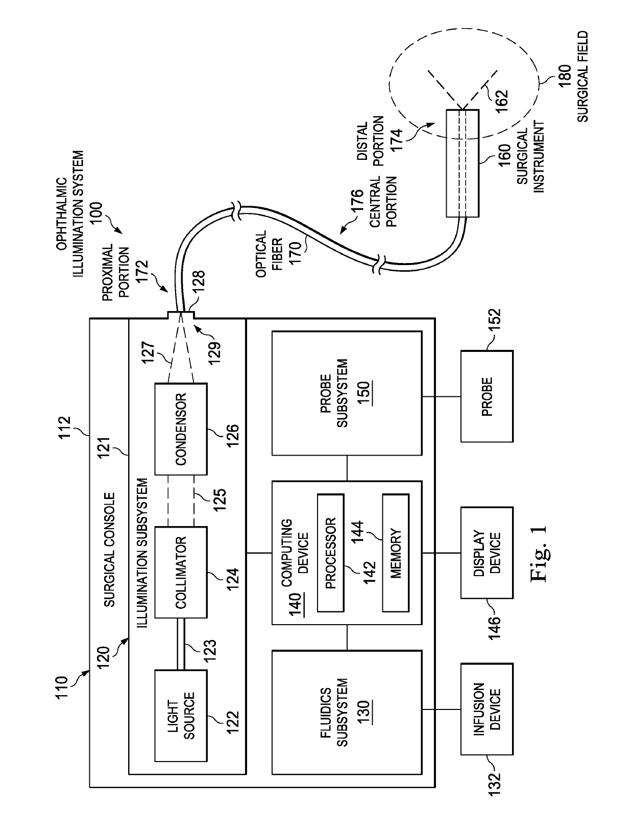
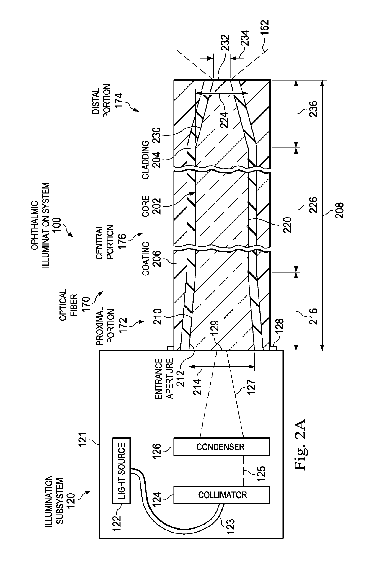
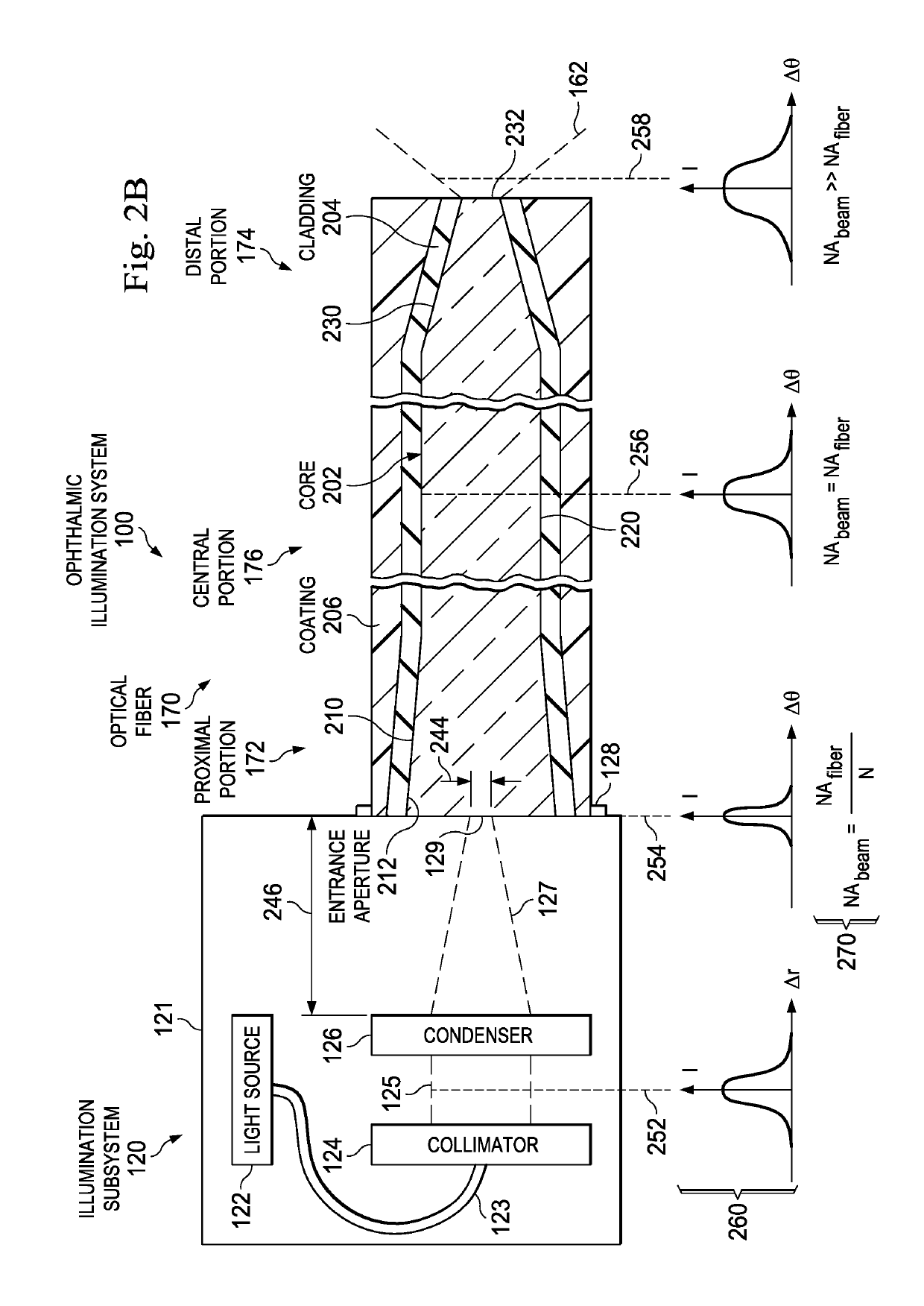
[0024]The present disclosure describes devices, systems, and methods of optically coupling a light beam into an optical fiber in a manner that tolerates unintended angular or lateral misalignment of the light beam. A light source can generate a light beam for illuminating a surgical field, such as a patient's eye. A condenser can focus and direct the light beam towards the optical fiber. The condensed beam may be misaligned in some instances. The optical fiber includes a tapered proximal portion con...


PUM


Abstract

An ophthalmic illumination system can include an optical fiber configured to transmit a light beam output by a light source and focused by a condenser. The optical fiber can include proximal, distal, and central portions. The proximal portion can be configured to receive the light beam focused by the condenser. The distal portion can be configured to emit the light beam to illuminate a surgical field. The central portion can extend between the proximal and distal portions. A core diameter of the proximal portion can be larger than core diameters of the central and distal portions. An ophthalmic illumination method can include focusing, using a condenser, a light beam emitted by a light source onto a proximal portion of an optical fiber. The method can also include transmitting, using the optical fiber, the light beam to a surgical field.

Description

BACKGROUND[0001]Technical Field[0002]Embodiments disclosed herein can be related to ophthalmic illumination systems. More specifically, embodiments described herein can relate to illuminating a surgical field, such as a patient's eye, during ophthalmic procedures using an optical fiber having a tapered proximal portion. The tapered proximal portion can allow the optical fiber to efficiently receive a misaligned light beam.[0003]Related Art[0004]Ophthalmic microsurgical procedures can require precision cutting and / or removing of various body tissues of the patient's eye. During the procedures, ophthalmic illumination devices can provide light for the surgical field. A user, such as a surgeon or other medical professional, can insert the device into the eye to illuminate the inside of the eye. A light source and other illumination optics, such as a collimator and a condenser, direct a light beam towards an optical fiber of the illumination device.[0005]During assembly of the illuminat...

Claims


Application Information

Patent Timeline
Patent Type & Authority Patents(United States)
IPC IPC(8): A61B3/00A61F9/007F21V8/00
CPCA61B3/0008G02B6/0006G02B6/0008A61B90/30A61F9/007A61B2090/306
Inventor SMITH, RONALD T.MIRSEPASSI, ALIREZA
Owner ALCON INC
Why Eureka
Try Eureka