Inertia measurement module and triaxial accelerometer

a technology of inertia measurement module and triaxial accelerometer, which is applied in the direction of speed/acceleration/shock measurement, measurement devices, instruments, etc., can solve the problems of reducing the detection accuracy, reducing the change amount of capacitors, and reducing detection accuracy, so as to improve the detection accuracy of capacitors and increase the coupling between axes

Active Publication Date: 2019-11-12
WEIFANG GOERTEK MICROELECTRONICS CO LTD
View PDF17 Cites 1 Cited by
  • Summary
  • Abstract
  • Description
  • Claims
  • Application Information

AI Technical Summary

Benefits of technology

[0005]In order to solve the problems in the prior art, the present invention provides an inertial measurement module which is simple in structure and high in measurement accuracy.
[0017]In the inertial measurement module provided by the present invention, the movement of a certain axis (X-axis and Y-axis) in a plane is not affected by the eccentricity of the structure, so that the movement of the X-axis or the Y-axis is a linear movement, without increasing the coupling between axes. On the other hand, the displacement amount of the mass block in the X-axis axis and Y-axis directions cannot be reduced, thereby improving the detection accuracy of a capacitor.

Problems solved by technology

On one hand, this movement increases the coupling between axes, and on the other hand, the change amount of a capacitor is reduced, thereby greatly reducing the detection accuracy.
Moreover, during the detection of y-axis acceleration, the actual movement may be a swinging movement, rather than a linear movement due to this characteristic of the structure, further reducing the detection accuracy.

Method used


Image

  • Inertia measurement module and triaxial accelerometer
  • Inertia measurement module and triaxial accelerometer
  • Inertia measurement module and triaxial accelerometer

Examples


embodiment i

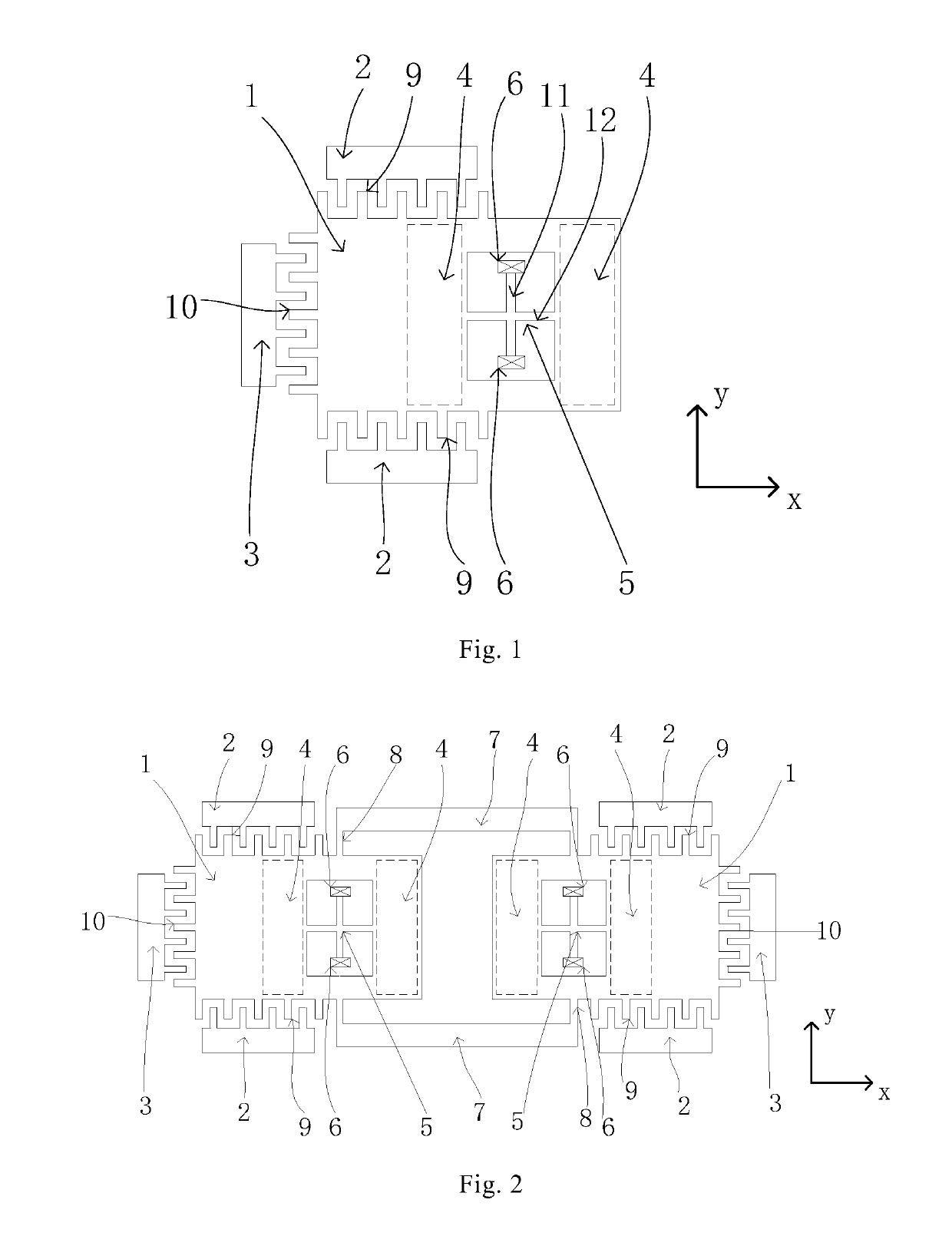
[0028]Referring to FIG. 1, the present invention provides an inertial measurement module in a triaxial accelerometer. The inertial measurement module comprises a substrate (not shown in the drawing) on which a component such as a circuit of the inertial measurement module may be arranged. The substrate is provided with a first pole piece 4 (represented by a dotted line in the drawing) as a lower electrode.

[0029]The inertial measurement module provided by the present invention further comprises a mass block 1 located above the substrate and a support system 5 for supporting the mass block 1 above the substrate. The support system 5 is composed of elastic beams comprising a first elastic beam 12 and a second elastic beam 11. The first elastic beam 12 and the second elastic beam 11 are fixed together in a crossed manner; preferably, the fixed connecting point thereof is located in the middles of the two elastic beams; and more preferably, the first elastic beam 12 is located in the X-a...

embodiment ii

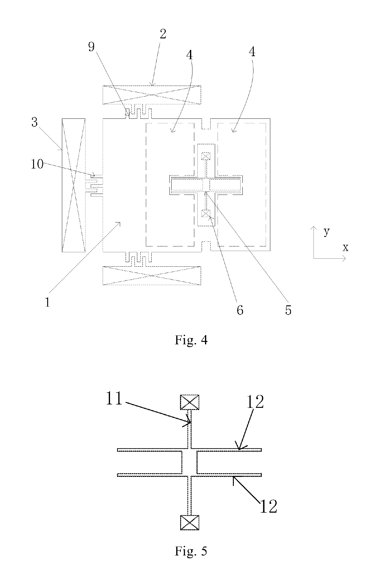
[0044]Referring to FIG. 4, the present invention provides an inertial measurement module in a triaxial accelerometer. The inertial measurement module comprises a substrate (not shown in the drawing) on which a component such as a circuit of the inertial measurement module may be arranged. The substrate is provided with a first pole piece 4 (represented by a dotted line in the drawing) as a lower electrode.

[0045]The inertial measurement module provided by the present invention further comprises a mass block 1 located above the substrate and a support system 5 for supporting the mass block 1 above the substrate. The support system 5 may be composed of elastic beams through which the mass block 1 is supported above the substrate in a suspending manner.

[0046]Referring to FIG. 5, the elastic beams comprise two first elastic beams 12 in the X-axis direction and a second elastic beam 11 in the Y-axis direction; and the two first elastic beams 12 and the second elastic beam 11 are fixed tog...

embodiment iii

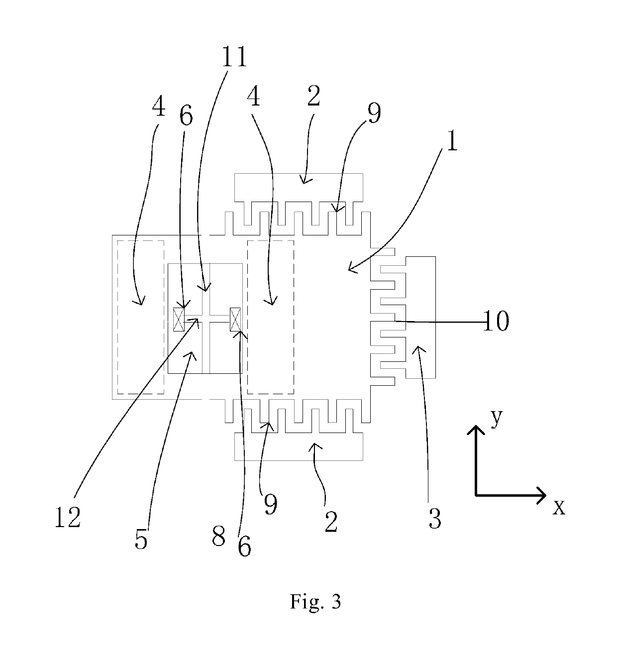
[0063]Referring to FIG. 8, the present invention provides a Z-axis structure in an accelerometer. The Z-axis structure comprises two structurally symmetric inertial measurement modules. Each inertial measurement module comprises a substrate (not shown in the drawing) on which a component such as a circuit of the inertial measurement module may be arranged. The substrate is provided with a first pole piece 4 (represented by a dotted line in the drawing) as a lower electrode.

[0064]The inertial measurement module further comprises a mass block 1 located above the substrate and a support system 5 for supporting the mass block 1 above the substrate. The support system 5 is composed of elastic beams comprising a first elastic beam 12 and a second elastic beam 11. The first elastic beam 12 and the second elastic beam 11 are fixed together in a crossed manner. Preferably, the fixed connecting point is located in the middles of the two elastic beams, wherein the first elastic beam 12 is loca...


PUM


Abstract

An inertia measurement module and three-axis accelerometer, comprising a first pole piece (4) located on a substrate and a mass block (1) suspendingly connected above the substrate via elastic beams (11, 12); the elastic beams (11, 12) includes a first elastic beam (12) and a second elastic beam (11), two ends of the second elastic beams (11) being connected to an anchor point (6) of the substrate, two ends of the first elastic beam (11) being connected to the mass block (1); a center of the first elastic beam (12) and / or the second elastic beam (11) deviates from a center of gravity of the mass block (1); the mass block (1) is further provided with a first movable electrode (9) and a second movable electrode (10) in a Y-axis and an X-axis direction; the movement of one axis in a plane of the inertia measurement module cannot be affected by an eccentric structure feature, such that both X-axis movement and Y-axis movement are linear movements, thus not intensifying an inter-axis coupling, and also not reducing displacement of a mass block on the X-axis and the Y-axis, thus improving capacitance detection precision.

Description

CROSS REFERENCE TO RELATED APPLICATIONS[0001]This application is a national stage application, filed under 35 U.S.C. § 371, of International Application No. PCT / CN2015 / 084970, filed Jul. 23, 2015, which claims priority to Chinese Application No. 201410826621.5 filed Dec. 25, 2014, Chinese Application No. 201410826551.3 filed Dec. 25, 2014, and Chinese Application No. 201510050223.3 filed Jan. 30, 2015, the contents of all of which as are hereby incorporated by reference in their entirety.BACKGROUND[0002]The present invention relates to the field of micro-electromechanical systems (MEMS), and more particularly, relates to a micro-electromechanical inertial measurement module. The present invention further relates to a triaxial accelerometer.[0003]A micro-electromechanical accelerometer is an MEMS technology-based inertial device for measuring the linear movement acceleration of an object in movement. It has the characteristics of being small in size, high in reliability, low in cost ...

Claims


Application Information

Patent Timeline
Patent Type & Authority Patents(United States)
IPC IPC(8): G01P15/125G01P15/18
CPCG01P15/18G01P15/125G01P2015/082G01P2015/0814G01P2015/0831
Inventor ZHANG, TINGKAI
Owner WEIFANG GOERTEK MICROELECTRONICS CO LTD
Why Eureka
Try Eureka