Cap removal for gate electrode structures with reduced complexity

a gate electrode and complexity technology, applied in the field of semiconductor devices, can solve the problems that the “fine tuning” of various types of transistor elements would not be possible or would require significant efforts during previous manufacturing stages, and achieve the effects of reducing material loss, reducing overall process complexity, and superior process conditions

Active Publication Date: 2019-11-12
GLOBALFOUNDRIES U S INC
View PDF4 Cites 1 Cited by
  • Summary
  • Abstract
  • Description
  • Claims
  • Application Information

AI Technical Summary

Benefits of technology

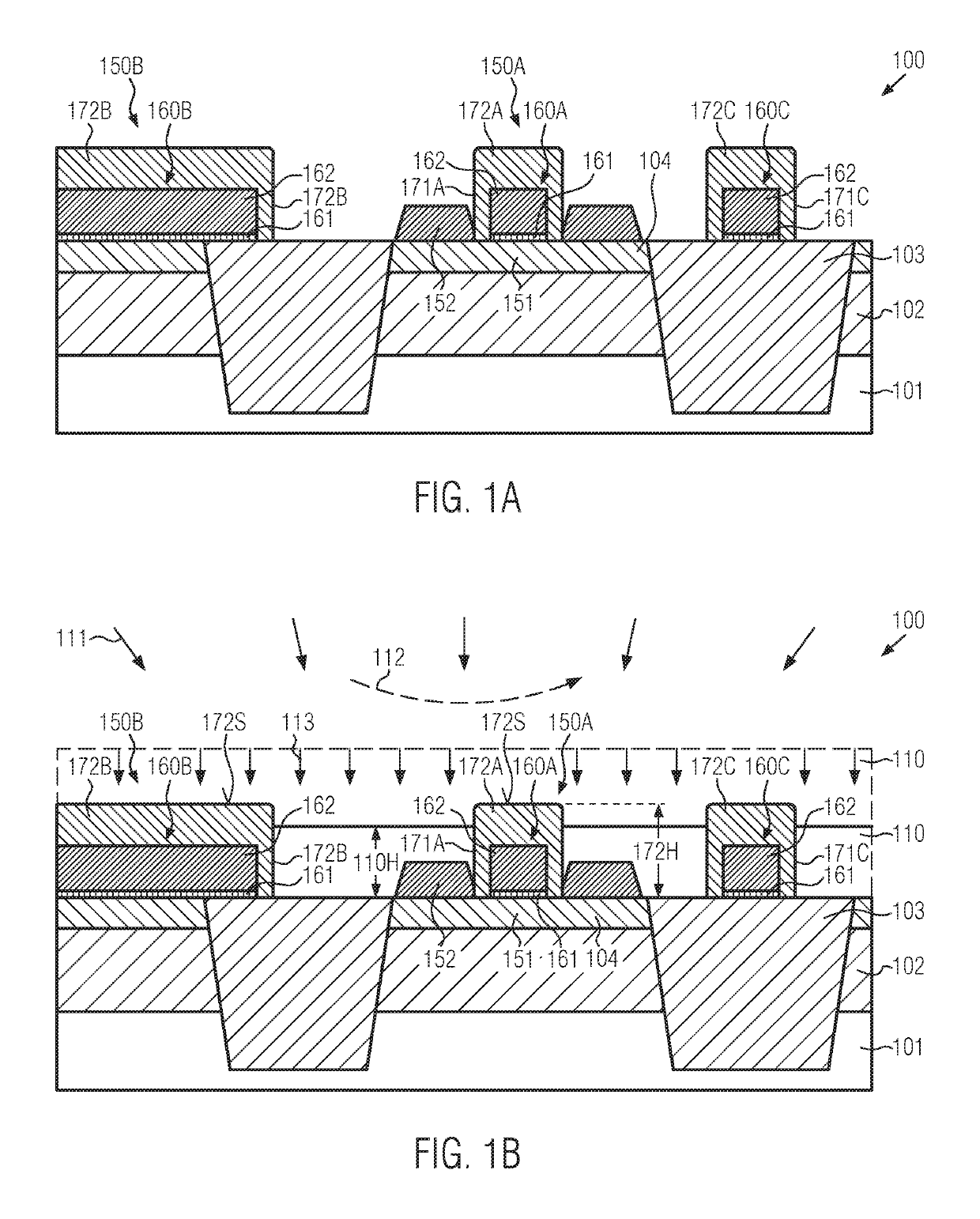
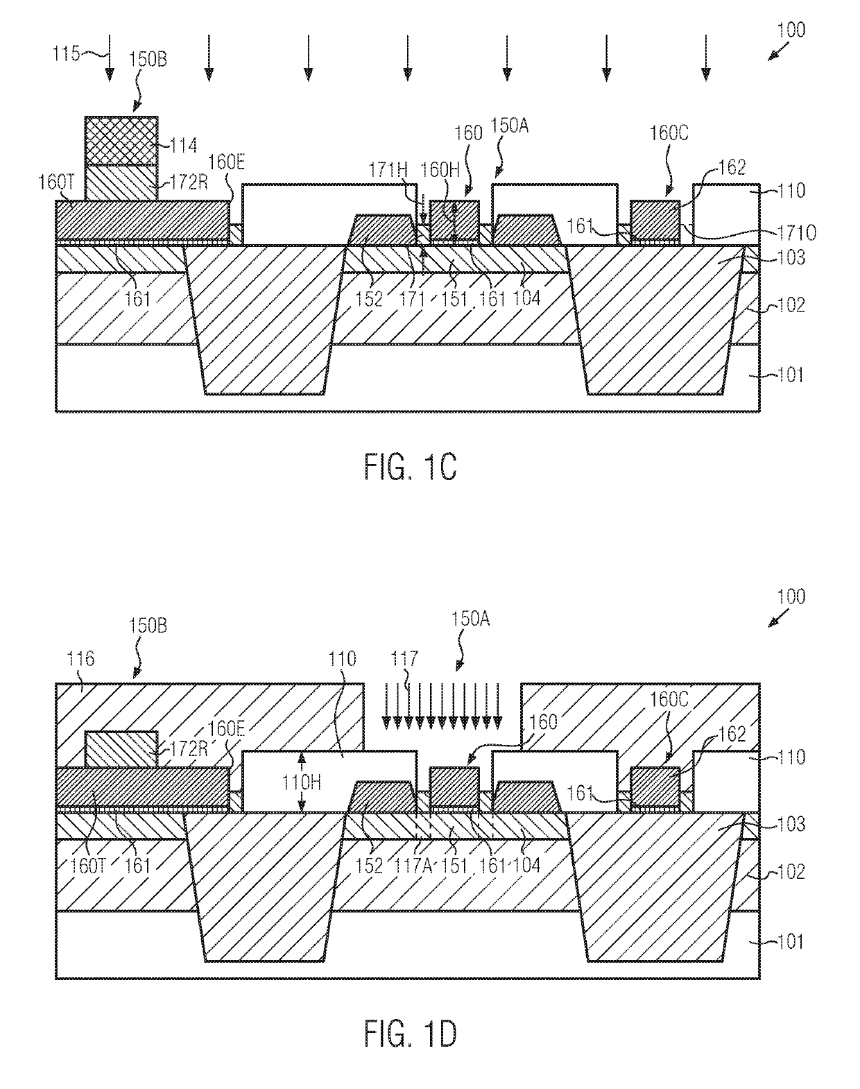
[0016]Generally, the present disclosure is based on the concept that the relatively complex process sequence for removing a capping material from gate electrode structures prior to the process of incorporating a highly conductive metal semiconductor compound may be made significantly more efficient by embedding the semiconductor device in an appropriate fill material, such as an oxide material, thereby reducing material loss in raised drain and source regions while also reducing the risk of generating critical device areas, which may result in unwanted short circuits or bridges after having incorporated the highly conductive metal semiconductor compound. Moreover, by using the fill material, the process of providing sacrificial protective spacer elements may, in some illustrative embodiments, be omitted, thereby also reducing overall process complexity. Furthermore, in some illustrative embodiments disclosed herein, the removal process may be based on a plasma-assisted anisotropic etch process rather than using a wet chemical etch chemistry as in conventional strategies, thereby also contributing to superior process conditions and reduced process related failures. In some illustrative embodiments disclosed herein, the plasma-assisted etch process may be performed on the basis of an etch mask, which may additionally ensure that the capping material may be preserved in areas in which the formation of a metal semiconductor compound is to be avoided. For example, a corresponding mask for forming resistor elements may be efficiently used during the corresponding etch process, thereby avoiding an additional process sequence for defining metal semiconductor free areas in resistors, as required in conventional approaches. Consequently, if considered appropriate, respective additional spacer elements may no longer be used.
[0017]Furthermore, the previously provided fill material may also be advantageously used, after having removed the capping material and thereby also having reduced a height of initially provided spacer elements, as an implantation mask for introducing additional implant species, such as dopants, counter-dopants, diffusion enhancing or mitigating species and the like, in a locally precisely defined manner, i.e., through the height-reduced spacer elements, thereby providing additional degrees of freedom for adjusting overall transistor characteristics. The additional parameter adjustment may be highly advantageous in complex integrated circuits, in which different “flavors” of transistor elements may result in superior performance of specific electronic functions. For example, additional doping, counter-doping and the like may be applied in a spatially localized manner for basic semiconductor material, wherein any such “fine tuning” of various types of transistor elements would not be possible or would require significant efforts during previous manufacturing stages.
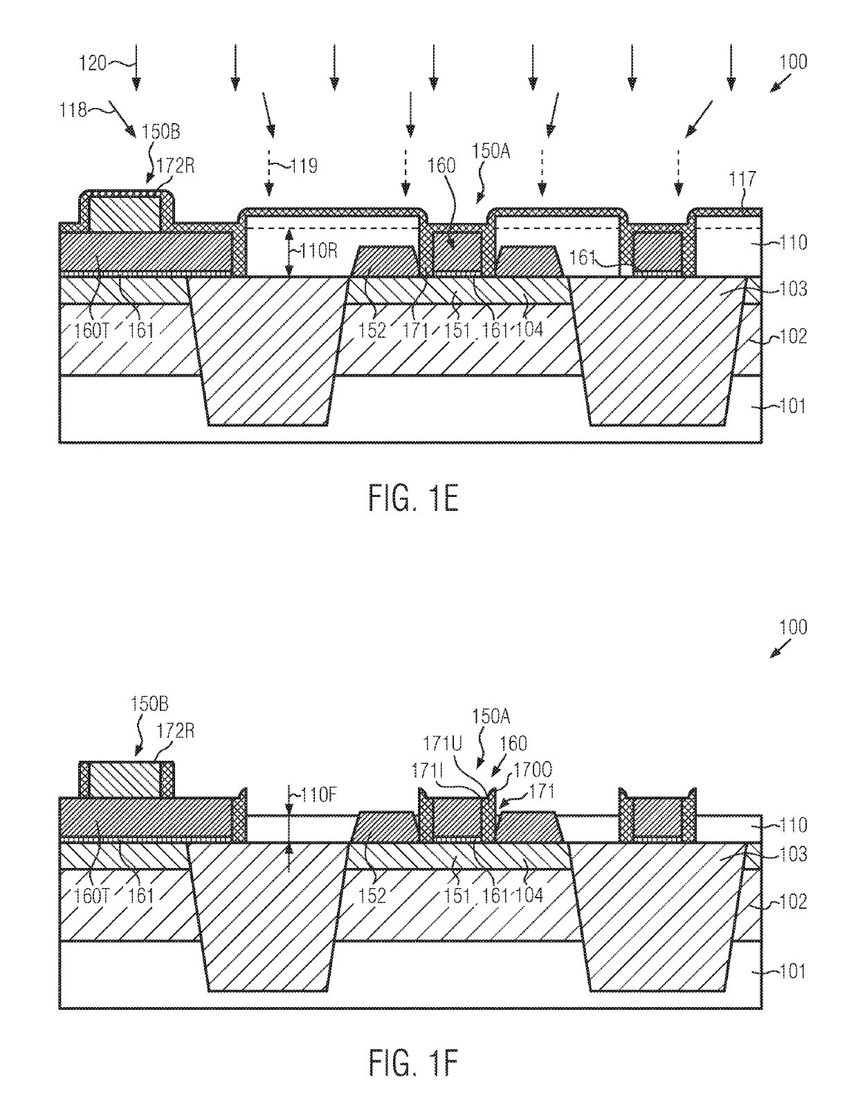
[0018]After any such optional implantations of specific species, the spacer elements reduced in height during the previous anisotropic capping material removal may be refilled and patterned, thereby providing an increased process window with respect to typical failure mechanisms frequently associated with the removal of the capping material based on a wet chemical etch recipe in combination with a sacrificial protective spacer element, as, for instance, discussed above when referring to the conventional approach.
[0019]Consequently, the plasma-assisted process for removing the capping material provides superior control of the height adjustment of spacer elements and thus provides, in combination with the fill material, conditions for implanting additional implant species for fine-tuning transistor characteristics in a moderately late manufacturing stage. Furthermore, the significant material loss of the raised drain and source regions that is typically experienced in conventional strategies based on wet chemical recipes and sacrificial oxide spacers may be significantly reduced or substantially avoided due to the presence of the fill material.
[0020]Moreover, the risk of forming metal semiconductor compound bridges between gate electrode structures and respective contact elements to be formed in a later stage may be reduced. Furthermore, generally, the number of process steps required may be reduced, thereby achieving reduced manufacturing costs. As a further effect of providing the fill material, superior device topography after the removal of the capping material may be obtained, which may also contribute to superior process conditions upon forming a contact level including appropriate dielectric material(s), possibly with strain-inducing effect. The improved surface topography may even provide conditions for forming contact elements in critical device areas, for instance near recessed areas of isolation regions, which may typically suffer from a pronounced surface topography in conventional approaches and which may not allow the formation of contact elements or which would otherwise contribute to a high risk of generating contact failures. Due to the equalizing effect of the fill material, the formation of contact elements in such critical areas may no longer be prohibited by design rules and thus more efficient designs may be accomplished.

Problems solved by technology

For example, additional doping, counter-doping and the like may be applied in a spatially localized manner for basic semiconductor material, wherein any such “fine tuning” of various types of transistor elements would not be possible or would require significant efforts during previous manufacturing stages.

Method used


Image

  • Cap removal for gate electrode structures with reduced complexity
  • Cap removal for gate electrode structures with reduced complexity
  • Cap removal for gate electrode structures with reduced complexity

Examples


Embodiment Construction

[0028]Various illustrative embodiments of the invention are described below. In the interest of clarity, not all features of an actual implementation are described in this specification. It will of course be appreciated that in the development of any such actual embodiment, numerous implementation-specific decisions must be made to achieve the developers' specific goals, such as compliance with system-related and business-related constraints, which will vary from one implementation to another. Moreover, it will be appreciated that such a development effort might be complex and time-consuming, but would nevertheless be a routine undertaking for those of ordinary skill in the art having the benefit of this disclosure.

[0029]The following embodiments are described in sufficient detail to enable those skilled in the art to make use of the invention. It is to be understood that other embodiments would be evident, based on the present disclosure, and that system, structure, process or mech...


PUM


Abstract

The present disclosure relates to manufacturing techniques and respective semiconductor devices in which the capping material of gate electrode structures may be removed together with portions of the capping material of resistors on the basis of a highly controllable directional etch process, wherein raised drain and source regions may be protected on the basis of a fill material.

Description

BACKGROUND1. Field of the Disclosure[0001]Generally, the present disclosure relates to semiconductor devices and respective manufacturing techniques in which transistor elements may be formed on the basis of a complex transistor architecture including raised drain and source regions in combination with gate electrode structures that need to be exposed in a moderately late manufacturing stage.2. Description of the Related Art[0002]Significant progress has been made in the field of semiconductor devices, such as integrated circuits, by continuously reducing the dimensions of the individual components, such as circuit elements in the form of transistor elements, capacitors, resistors and the like. For example, in currently available highly sophisticated integrated circuits, several hundred millions or more circuit elements, mainly transistor elements, may be formed on a single semiconductor chip, thereby offering the potential of integrating more and more functions into a single semico...

Claims


Application Information

Patent Timeline
Patent Type & Authority Patents(United States)
IPC IPC(8): H01L21/311H01L21/3105H01L27/11H01L29/66H01L21/266H01L29/786H01L29/08H01L21/762
CPCH01L29/0847H01L21/31144H01L27/1112H01L21/31053H01L29/78621H01L29/6653H01L21/266H01L29/66772H01L21/31116H01L21/76283H01L29/66757H01L27/1203H01L21/84H01L21/823418H01L21/823437H01L27/088H01L29/66492H01L29/66628H01L29/165H01L29/7848Y02P80/30H10B10/15
Inventor THEES, HANS-JUERGENBAARS, PETER
Owner GLOBALFOUNDRIES U S INC
Why Eureka
Try Eureka