Cementing casing in a large diameter mud drilled well

a cementing casing and large-diameter technology, which is applied in the direction of drilling accessories, borehole/well accessories, constructions, etc., can solve the problems of different problems, endanger the underground sources of drinking water, and the mud at the bottom of the well gets in the way, and achieves the effect of higher velocity

Active Publication Date: 2019-12-03
YOUNGQUIST BROS INC
View PDF11 Cites 4 Cited by
  • Summary
  • Abstract
  • Description
  • Claims
  • Application Information

AI Technical Summary

Benefits of technology

[0028]It is another object of the invention to reverse the direction of mud flow to increase the velocity of drilling mud with cuttings suspended therein to the top of the wellbore to remove more cuttings or suspended solids.
[0029]It is yet another object of the present invention to remove excessive wall cake, heavy mud and cuttings by vacuuming the bottom of the wellbore.
[0030]It is still another object of the present invention to use bi-directional agitators attached to the outside of the casing so that upon rotation and reciprocating of the casing, the bi-directional agitators will help clear the annulus between the casing and the wellbore.
[0033]By using this reverse direction flow, the velocity of the drilling mud returning to the surface reaches up to 250 ft / min. The increased velocity makes it possible to lift heavier drilling mud and cuttings out of the well.

Problems solved by technology

Different problems are incurred when attempting to use the same type of equipment to drill injection wells to depths of about 3,000 ft.
Each class of injection wells is based on the type and depth of the injection activity, and the potential for that injection activity to result in endangerment of underground sources of drinking water.
When attempting to cement casing in place in large injection wells, the mud at the bottom of the well gets in the way and interferes with the cement.
Also, cuttings in the mud have a tendency to settle out at the bottom of the well
If normal oil field technology is used in the drilling of large diameter injection wells, the mud will not flow upward at a fast enough rate to lift the cuttings with the drilling mud.
Also, in large diameter waste water disposal wells, clay that has been drilled and the drilling mud have a tendency to combine and form wall cake on the side of the borehole.
Wall cake will interfere with the cementing of large diameter casing.
If the cement becomes mixed with cuttings, drilling mud and clay, it will not form a good bond with the casing.
Also, if the drilling mud, clay and cuttings are not removed, the cement will tend to channel in the annulus between the borehole and the casing.
This process potentially can take several days.
During that time, the cuttings that are suspended in the drilling mud have a tendency to settle to the bottom of the well.
Also, clay in the formation may expand and sink in the drilling fluid.
The problem with the method just described in drilling large diameter holes is a sufficient upward velocity of the drilling mud to carry the cuttings to the is not obtainable with currently available surface mud handling equipment.
The upward velocity of the drilling mud is insufficient to carry the cuttings to the surface as necessary.
This is insufficient to raise drill cuttings and heavy particles to the surface.
In the period of time that passes between the conditioning of the well (i.e., pumping of drilling mud) and starting the cement pump, there is a non-uniform settling of cuttings and other particles in the bottom portion of the wellbore.
This is because there are un-cemented voids in the area between the outside of the casing and the wellbore.

Method used


Image

  • Cementing casing in a large diameter mud drilled well
  • Cementing casing in a large diameter mud drilled well
  • Cementing casing in a large diameter mud drilled well

Examples


Embodiment Construction

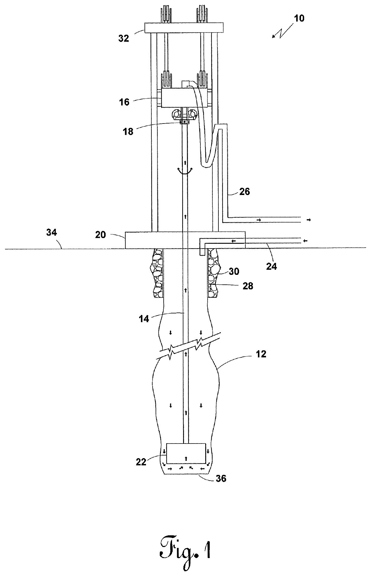
[0044]Referring to FIG. 1, a drilling rig 10 is pictorially illustrated above a wellbore 12. The wellbore 12 is for a large diameter waste water disposal well. Such large diameter disposal wells may be about sixty inches in diameter at the top and be reduced down to twenty-four inches in diameter at the bottom. Such large diameter wells can range from 20 inches in diameter to 90 inches in diameter.

[0045]A drill pipe extends down from the top head drive 16 and the drill pipe connection 18 through the drilling floor 20. The top head drive 16 rotates the drilling pipe 14 which has on the lower end thereof a drill bit 22. Because the borehole being drilled has a large diameter (approximately sixty-two inches), the drill bit 22 will be much larger in diameter than the drill pipe 14.

[0046]Drilling mud such as Bentonite flows into the wellbore 12 through drilling mud tubing 24. The drilling mud flows downward in the wellbore 12 in through the drill bit 22, up the drill pipe 14, through dri...


PUM


Abstract

A method of cementing casing in a large diameter mud drilled well is shown. A drilling rig turns drill pipe with sufficient down pressure being applied to a drill bit to drill a large diameter borehole. Initially drilling mud flows down the annulus between the drill pipe and borehole, then back up the drill pipe. An air pressure line in the drill pipe creates a suction at the drill bit. Direction of flow of drilling mud is reversed when the drill pipe is replaced with casing. Cuttings and heavy mud are removed from the borehole by bi-directionally rotating a casing while reciprocating up and down near a bottom of the borehole. When the desired mud weight and viscosity is reached, mud flow is stopped and cement is applied through a tremie tube.

Description

BACKGROUND OF THE INVENTION1. Field of the Invention[0001]This invention relates generally to the drilling of a large diameter well and, more particularly, to the cementing casing in a large diameter mud drilled well.2. Description of the Prior Art[0002]An oil and gas well is any perforation through the earth's surface designed to find and release oil and / or gas hydrocarbons. A well is created by drilling a hole into the earth with a drilling rig that rotates a drill string with a bit attached to the lower end. After the hole is drilled to a prescribed depth, sections of steel tubing known as casing are set in the hole. The casing is slightly smaller in diameter than the borehole. The casing provides structural integrity to the newly drilled wellbore and isolates zones from each other and from the surface. As the well is drilled deeper, smaller bits and smaller sized casing is used. Modern wells often have three to five sets of subsequently smaller hole sizes being drilled, each dri...

Claims


Application Information

Patent Timeline
Patent Type & Authority Patents(United States)
IPC IPC(8): E21B33/14E21B37/02E21B21/12E21B21/00E21B7/00
CPCE21B33/14E21B21/00E21B21/12E21B37/02E21B7/00E21B43/10E21B21/01
Inventor YOUNGQUIST, JR., HARVEY BRUCEYOUNGQUIST, BRETT ALAN
Owner YOUNGQUIST BROS INC
Why Eureka
Try Eureka