Gold pigment with high color strength

a high-color strength, gold pigment technology, applied in the field of gold pigments, can solve the problems of difficulty in properly realizing gold color with lesser red tones required by consumers, and the limitation that gold color is obtained by a combination of white titanium dioxide and red iron oxide in general, and achieves less red tones, excellent gloss, and less reddish.

Active Publication Date: 2019-12-31
CQV
View PDF26 Cites 0 Cited by
  • Summary
  • Abstract
  • Description
  • Claims
  • Application Information

AI Technical Summary

Benefits of technology

[0021]The gold pigment according to the present disclosure can additionally include a manganese-containing oxide coating layer such as a blackish brown MnO in addition to a TiO2 coating layer and an Fe2O3 coating layer, thereby obtaining a gold color with less red tones.
[0022]In addition, the gold pigment according to the present disclosure is less reddish, has excellent gloss, and has a strong sparkling impact.

Problems solved by technology

However, only limited gold color can be obtained with white titanium dioxide and red iron oxide alone, and therefore it is difficult to properly realize gold color which has lesser red tones required by consumers.
In the case of the gold pigment shown in FIGS. 1 and 2, there is a limitation that gold color is obtained by a combination of white titanium dioxide and red iron oxide in general, except that a coating layer formed of colorless SiO2 is formed in an intermediate layer.

Method used


Image

  • Gold pigment with high color strength
  • Gold pigment with high color strength

Examples


example 1

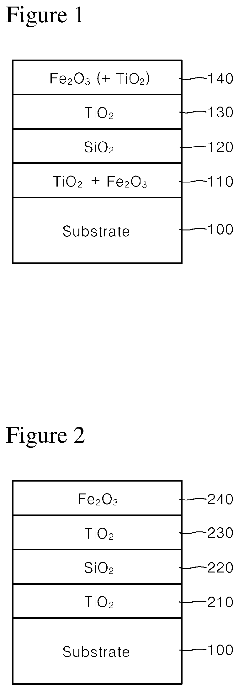
[0052]100 g of synthetic mica flakes having a particle size of 5 to 560 μm were introduced into 1 L demineralized water and stirred to form a slurry. Then, after the slurry was heated to 75° C., the pH of the slurry was adjusted to 1.7 by adding an HCl solution (Formation of substrate slurry).

[0053]Then, 30 g of SnCl4 solution (SnCl4 content 11 wt. %) was weighed and titrated in the slurry at a constant rate over 1 hour while the pH was kept constant at 1.7 with 30% NaOH diluent.

[0054]Then, 300 g of TiCl4 solution (TiCl4 content 33 wt. %) was weighed and titrated in the slurry over 8 hours while the pH was kept constant at 1.7 with 30% NaOH diluent. After titration, the mixture was refluxed for 10 minutes, and the pH was adjusted to 7.0 with 20% NaOH diluent (Formation of first coating layer).

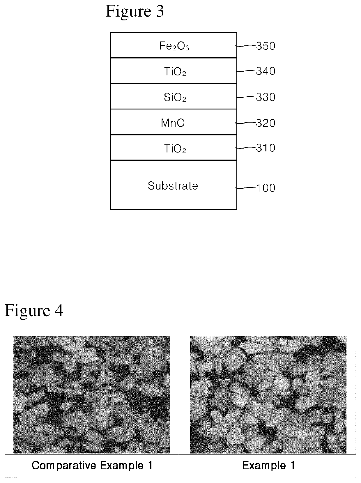
[0055]Then, 100 g of MnCl2 solution (MnCl2 content 3 wt. %) was weighed and titrated in the slurry over 2 hours while the pH was kept constant at 6.0 to 8.0 with 30% NaOH diluent. After titrati...

example 2

[0063]100 g of synthetic mica flakes having a particle size of 5 to 560 μm were introduced into 1 L demineralized water and stirred to form a slurry. Then, after the slurry was heated to 75° C., the pH of the slurry was adjusted to 1.7 by adding an HCl solution (Formation of substrate slurry).

[0064]Then, 300 g of TiCl4 solution (TiCl4 content 33 wt. %) was weighed and titrated in the slurry over 8 hours while the pH was kept constant at 2.4 with 30% NaOH diluent. After titration, the mixture was refluxed for 10 minutes, and the pH was adjusted to 7.0 with 20% NaOH diluent (Formation of first coating layer).

[0065]Then, 100 g of MnCl2 solution (MnCl2 content 3 wt. %) was weighed and titrated in the slurry over 2 hours while the pH was kept constant at 6.0 to 8.0 with 30% NaOH diluent. After titration, the mixture was refluxed for 10 minutes, and the pH was adjusted to 7.5 with 20% NaOH diluent (Formation of second coating layer).

[0066]Then, 900 g of MgO.SiO2 solution (MgO.SiO2 content...


PUM

PropertyMeasurementUnit
pHaaaaaaaaaa
refractive indexaaaaaaaaaa
thicknessaaaaaaaaaa

Abstract

A gold pigment is disclosed. The gold pigment according to the present disclosure includes a substrate; a first coating layer formed on a surface of the substrate and including a metal oxide having a refractive index of more than 1.8; a second coating layer formed on the first coating layer and including an oxide containing manganese; a third coating layer formed on the second coating layer and including a colorless metal oxide having a refractive index of 1.8 or less; a fourth coating layer formed on the third coating layer and including a metal oxide having a refractive index of more than 1.8; and a fifth coating layer formed on the fourth coating layer and including Fe2O3.

Description

CROSS REFERENCE TO RELATED APPLICATION[0001]This present application is a national stage filing under 35 U.S.C § 371 of PCT application number PCT / KR2016 / 005824 filed on Jun. 2, 2016 which is based upon and claims the benefit of priority to Korean Patent Application No. 10-2015-0082060 filed on Jun. 10, 2015, in the Korean Intellectual Property Office. The disclosures of the above-listed applications are hereby incorporated by reference herein in their entirety.TECHNICAL FIELD[0002]The present disclosure relates to a gold pigment, and more particularly to a novel gold pigment in which reddish tone is lessened by controlling the lamination structure of coating layers and laminated materials thereof, thereby improving gold aesthetic.BACKGROUND ART[0003]Gold pigments are gold-colored pigments and are used for aesthetic effects in various fields. For example, it has been used in industrial applications such as wallpaper, laminate, plastic molding, leather coating, silk printing, offset ...

Claims


Application Information

Patent Timeline
Patent Type & Authority Patents(United States)
IPC IPC(8): A61K8/02A61K8/19C09D7/62A61Q1/04C09C1/00C09D167/00A61K8/29A61K8/25C08K9/02C08K3/34C08K3/22
CPCC09C1/0024A61K8/0233A61K8/19A61Q1/04C08K3/34A61K8/25C09D167/00C08K3/22A61K8/29C08K9/02C09D7/62A61K8/022C09C2220/106A61K2800/43C08K2003/2241C08K2003/2272C08K2003/2262C09C2200/102C09C3/063C01P2006/60C01P2006/62C01P2006/63C01P2006/64C09C1/0039C09C3/06C09C1/00
Inventor CHANG, KIL-WANLIM, KWANG-SOOCHOI, BYUNG-KILEE, JIN-HYOUNG
Owner CQV
Why Eureka
Try Eureka