
ESP motor with sealed stator windings and stator chamber

a stator winding and sealed technology, applied in the field of electric motors, can solve the problems of affecting windings, and accelerating so as to reduce or prevent the degradation of electrical insulation

Active Publication Date: 2020-01-21
BAKER HUGHES INC
View PDF19 Cites 5 Cited by
  • Summary
  • Abstract
  • Description
  • Claims
  • Application Information

AI Technical Summary

Benefits of technology

This patent describes a system and method for reducing degradation of electrical insulation in an electric motor used in an ESP system. The system includes a stator core made of a single-piece unit made of SMC material, with seals between the stator core sections and at the ends of the stator core. The stator core sections form a sealed stator chamber where fluids external to the motor are prevented from entering and degrading the stator windings. The stator chamber contains an expansion chamber that allows the dielectric oil to expand and contract with changes in temperature. The system also includes a rotor and stator installed in a separate motor housing, with the stator chamber containing the stator windings and the rotor chamber containing the motor oil. The system prevents well fluids from entering the motor and degrading the insulation of the windings. The technical effect of this system is to improve the reliability and durability of electric motors used in ESP systems.

Problems solved by technology

If wellbore fluids leak into the motor and come into contact with the electrical insulation, they can cause or accelerate degradation of the insulation.
Even if the well fluid does not get into the motor, the winding can also be adversely affected by the self-contained moisture in the motor oil.
These may further accelerate degradation of the electrical insulation.
Eventually, degradation of the windings' electrical insulation may be substantial enough to result in short circuits between turns of the windings, between different phases (i.e., between separate windings that are energized by different phases of the input power), and even between one of the phases and ground, any of which may reduce the efficiency of the motor or cause it to fail.

Method used


Image

  • ESP motor with sealed stator windings and stator chamber
  • ESP motor with sealed stator windings and stator chamber
  • ESP motor with sealed stator windings and stator chamber

Examples


Embodiment Construction

[0021]One or more embodiments of the invention are described below. It should be noted that these and any other embodiments described below are exemplary and are intended to be illustrative of the invention rather than limiting.

[0022]As described herein, various embodiments of the invention comprise systems and methods for reducing or preventing degradation of electrical insulation in an electric motor (e.g., for use in an ESP system), where a stator core is formed by elongated stator core sections having seals at each end to prevent wellbore fluids from entering the interior of the stator core and coming into contact with the insulated wires of the stator windings.

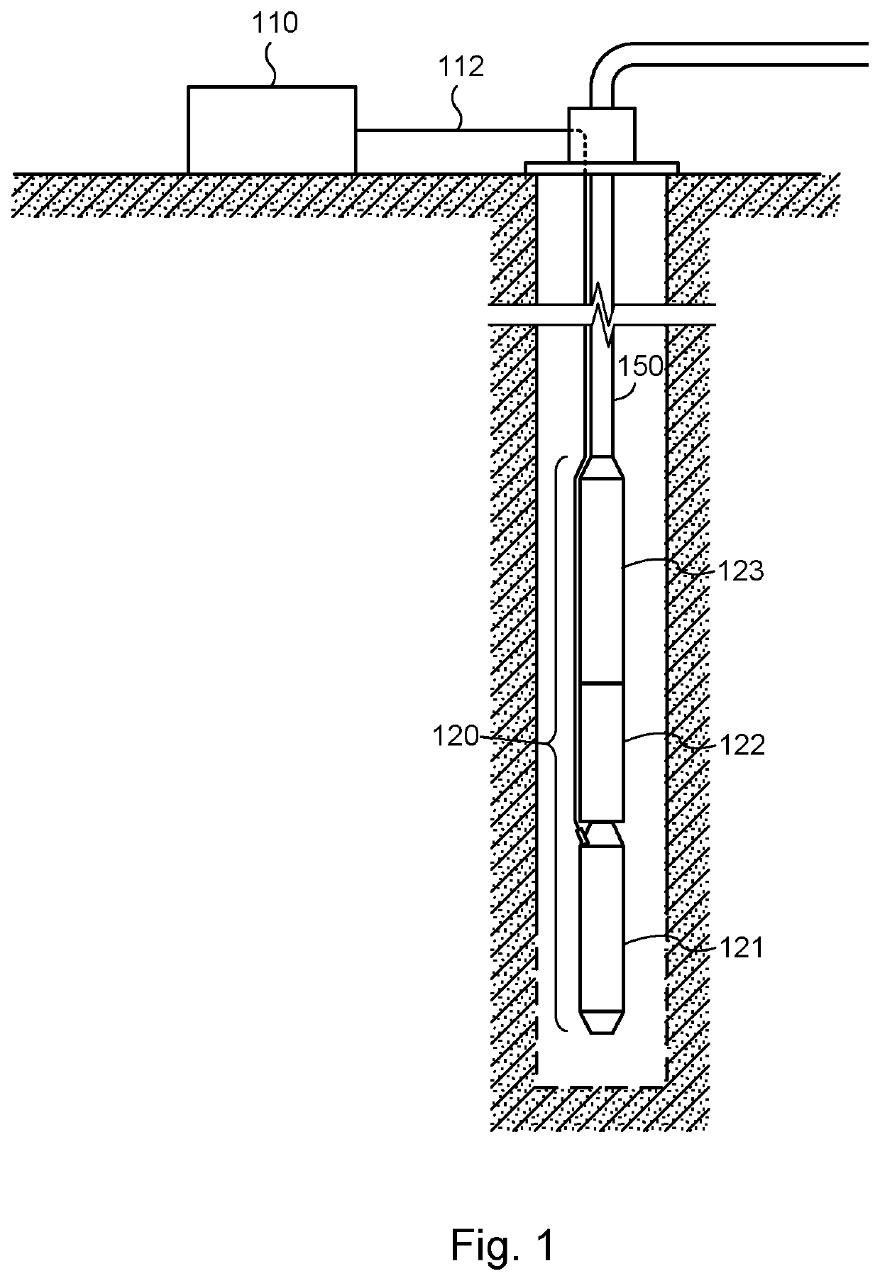
[0023]An ESP system is commonly positioned deep within a subterranean well. Referring to FIG. 1, a diagram illustrating an exemplary ESP system in which one embodiment of the present invention may be implemented is shown. In this embodiment, the ESP system is installed in a well for the purpose of producing oil or other f...


PUM


Abstract

Systems and methods for electric motor, where the stator core has one or more stator core sections, each of which is a single-piece unit formed of soft magnetic composite (SMC) material, and where the stator core sections are positioned end-to-end with seals at each end to form a plurality of stator slots, where each of the stator slots extends through each of the stator core sections and is in fluid communication with the others to form a sealed stator chamber. The sealed stator chamber may have an expansion chamber to allow expansion and contraction of dielectric fluid in the stator chamber while maintaining separation of the dielectric oil from lubricating oil which is within the motor but external to the stator chamber. The sealed stator chamber can prevent well fluids that leak into the motor from reaching the stator windings and degrading their insulation.

Description

CROSS-REFERENCE TO RELATED APPLICATIONS[0001]This application claims the benefit of U.S. Provisional Patent Application 62 / 305,447, filed Mar. 8, 2016 by Yong Li, et al., which is incorporated by reference as if set forth herein in its entirety.BACKGROUND[0002]Field of the Invention[0003]The invention relates generally to electric motors, and more particularly to systems and methods for reducing or preventing degradation of electrical insulation that separates the windings of a motor for use in such applications as submersible electric pump (ESP) systems by providing a hermetic seal that prevents the ingress of wellbore fluids into the motor's stator chamber where they can reach the windings.[0004]Related Art[0005]Artificial lift systems such as ESPs are commonly used in the production of oil from wells when the pressure in a producing geological formation is not sufficient to force the oil out of the formation and to the surface of the well. The ESP is positioned in the well, at or...

Claims


Application Information

Patent Timeline
Patent Type & Authority Patents(United States)
IPC IPC(8): H02K5/00F04B17/03H02K11/30H02K5/132F04B47/02H02K5/124H02K5/10H02K17/02H02K5/22
CPCH02K17/02H02K5/124H02K11/30F04B47/02F04B17/03H02K5/132H02K5/10H02K5/225F04B47/06H02K7/14H02K9/197H02K1/02H02K2201/15H02K2213/09E21B43/128H02K5/1285
Inventor LI, YONGKNAPP, JOHN M.REYNOLDS, JACKSON
Owner BAKER HUGHES INC
Learn More