Electric motor driving system and method

a driving system and electric motor technology, applied in the direction of battery/fuel cell control arrangement, electric devices, transportation and packaging, etc., can solve the problems of inability to maintain a prescribed preferable state of charge (soc) nor avoid degradation of a cell as well when driving the car, and the electric motor is unlikely to be driven steadily. achieve the effect of preventing or reducing degradation of a battery

Active Publication Date: 2021-09-07
DENSO CORP +1
View PDF13 Cites 2 Cited by
  • Summary
  • Abstract
  • Description
  • Claims
  • Application Information

AI Technical Summary

Benefits of technology

[0011]At least one of the first and second inverter control circuits includes an electric power controller to control sharing of electric power supplied from the first and second power supplies between the first and second inverters in accordance with a target electric power instruction (i.e., an instruction instructing the electric power controller about target electric power). Hence, according to one embodiment of the present invention, a shared amount of electric power supplied from the pair of electric power supplies (i.e., electric power of each of the electric power supplies) is controlled while supervising a SOC and voltages of the electric power supplies. Accordingly, the SOC can preferably be maintained while either preventing or reducing degradation of a battery in applicable one of the electric power supplies.
[0014]Yet another aspect of the present disclosure provides a novel electric motor driving system, in which the electric power controller located in a circuit on a feed-forward control side adjusts a voltage instruction so that an amount of electric power shared with an inverter located on the electric power supervising circuit side becomes equivalent to the instruction about target electric power. Subsequently, when the amount of electric power of the inverter on the electric power supervising circuit side comes near the instruction about target electric power, the electric power non-supervising circuit applies feedback control while outputting a voltage instruction so that an actual torque follows a torque instruction input to the main control unit 200 in accordance with a change in electric power. As a result, an amount of electric power of the inverter on the electric power non-supervising circuit side also approaches a desired level, thereby achieving power sharing.

Problems solved by technology

Further, since it assumes one-way charge and discharge control, the technology of JP-2007-14185-A can neither maintain a prescribed preferable state of charge (SOC) nor avoid degradation of a cell as well when driving the car.
As a result, motor control becomes complex and the electric motor is unlikely to be driven steadily.

Method used


Image

  • Electric motor driving system and method
  • Electric motor driving system and method
  • Electric motor driving system and method

Examples


Embodiment Construction

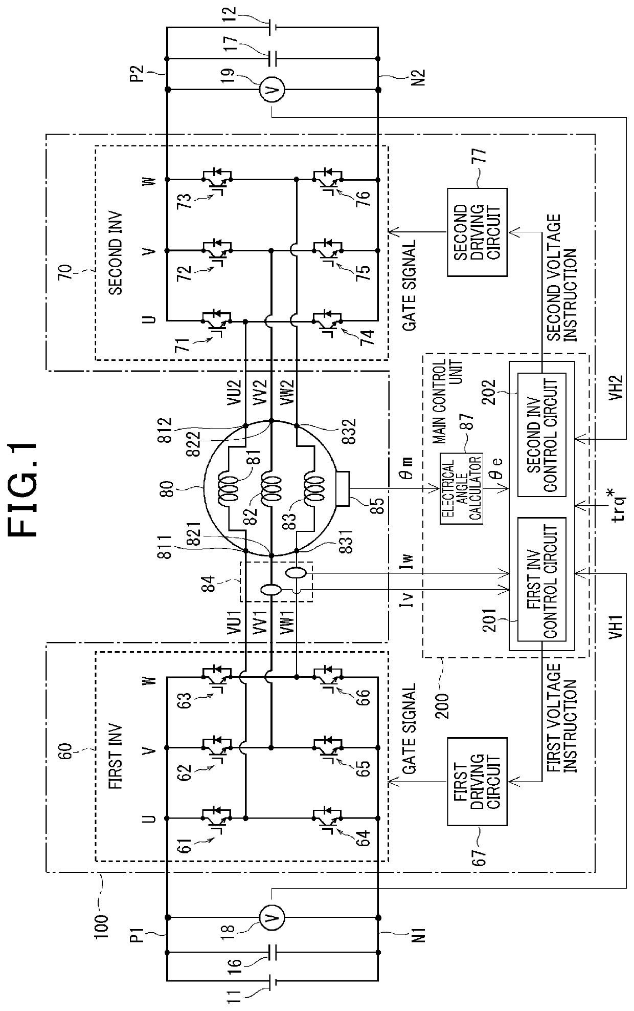
[0029]Herein below, various embodiments of the present invention are described with reference to several drawings. In the various embodiments, an electric motor driving system is included in a motor generator driving system that drives a motor generator (hereafter simply referred to as a MG) composed of a three-phase alternating current (AC) motor to act as a power source of a hybrid car or an electric motor car. Hence, the electric motor driving system is defined as a system that controls driving of the MG. A motor and an electric motor driving system are herein below sometimes referred to as a MG and a MG control system, respectively.

[0030]Referring now to the drawings, wherein like reference numerals designate identical or corresponding parts throughout the several views thereof, and in particular to FIG. 1, an overall structure of a system that employs a so-called dual electric power supply and dual inverter (i.e., a pair of electric power supplies 11 and 12, and a pair of first...


PUM


Abstract

In a so-called dual power source and dual inverter system, in which a pair of first and second inverters controls and drives a motor that includes multiple windings of phases each having open ends based on electric power supplied from a pair of power supplies, a motor driving system capable of appropriately allocating the electric power supplied from the pair of power supplies to the pair of inverters is provided. The motor driving system includes a pair of first and second inverter control circuits to generate a pair of first and second voltage instructions supplied to the first and second inverters based on a torque command, respectively. One of the first and second inverter control circuits includes a power controller that controls sharing of the electric power supplied from the first and second power supplies in accordance with a target electric power instruction.

Description

CROSS-REFERENCE TO RELATED APPLICATION[0001]This patent application is based on and claims priority to Japanese Patent Application 2018-054563, filed on Mar. 22, 2018 in the Japan Patent Office, the entire disclosure of which is hereby incorporated by reference herein.BACKGROUNDTechnical Field[0002]Embodiments of the present disclosure relate to an electric motor driving system and method that drives an electric motor by a pair of inverters.Related Art[0003]It is known that a pair of inverters is connected to both ends of an open winding of an alternating current (AC) motor, respectively, and drives the AC motor. For example, as discussed in Japanese Patent No. 3352182 (JP-3352182-B), an inverter system is composed of an electric circuit including a so-called dual electric power supply and dual inverter system. The so-called dual electric power supply and dual inverter system combines outputs of opposite polarities to each other issued from respective first and second inverters.[000...

Claims


Application Information

Patent Timeline
Patent Type & Authority Patents(United States)
IPC IPC(8): H02P4/00H02M7/5387B60L15/02B60L58/40
CPCH02P4/00H02M7/5387B60L15/025B60L58/40B60L2220/12H02P27/085H02P6/005H02P25/022B60L2220/54B60L2210/40B60L15/20B60L58/18B60L58/12H02P21/0003
Inventor OKA, HARUKAOMATA, RYUJIMATSUBARA, KIYOTAKANAKAMURA, MAKOTONOBE, DAIGO
Owner DENSO CORP
Why Eureka
Try Eureka