
Supercritical CO2 cycle coupled to chemical looping arrangement

a supercritical co2 cycle and looping combustion technology, applied in the field of systems and coupling a supercritical co2 cycle and a chemical looping combustion arrangement, can solve the problems of indirect combustion reaction, still present corrosion and pollution issues, and the “sweetening” process is typically very expensive, and the clc process is still inefficient in terms of energy production. efficiency and other issues

Active Publication Date: 2020-02-04
SAUDI ARABIAN OIL CO
View PDF14 Cites 0 Cited by
  • Summary
  • Abstract
  • Description
  • Claims
  • Application Information

AI Technical Summary

Benefits of technology

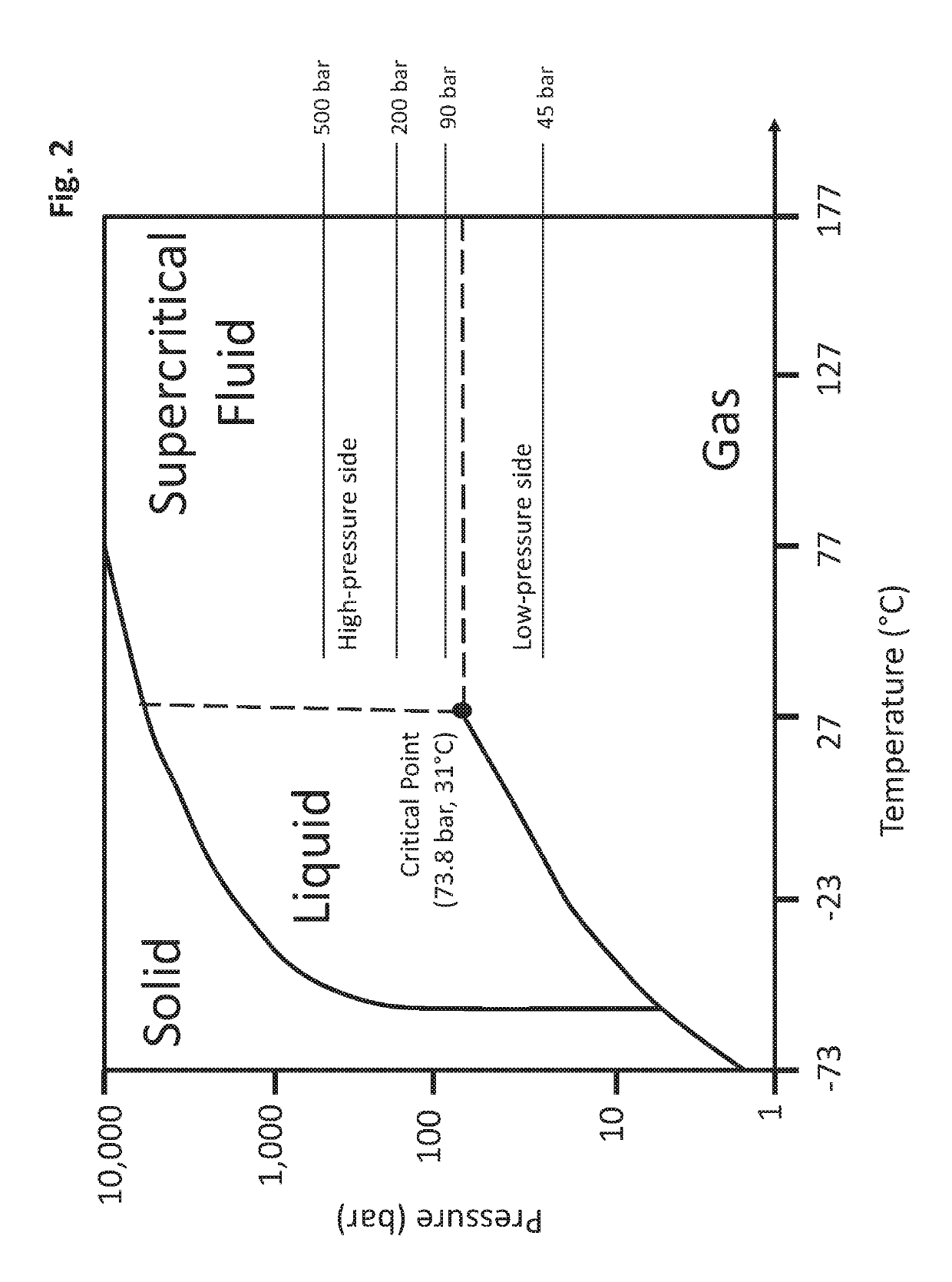
The patent text describes a compressor that has stages that help compress CO2 efficiently from a low-pressure side to a high-pressure side in a supercritical CO2 cycle. This compressor has multiple stages, which enable the transfer of compressed CO2 from one side to the other, resulting in improved performance and efficiency.

Problems solved by technology

H2S presents a problem during processing of the sour gas, as the corrosive nature of H2S can damage the mechanical parts of a system, and the processing of H2S can result in the production of SO2, which is an air pollutant.
However, combustion reactions, and specifically direct combustion reactions, still present the same corrosion and pollution issues associated with sour gas fuel.
However, this “sweetening” process is typically very costly.
Despite their advantages over direct combustion processes, CLC processes are still inefficient in terms of their ability to produce energy.

Method used


Image

  • Supercritical CO<sub>2 </sub>cycle coupled to chemical looping arrangement
  • Supercritical CO<sub>2 </sub>cycle coupled to chemical looping arrangement
  • Supercritical CO<sub>2 </sub>cycle coupled to chemical looping arrangement

Examples


Embodiment Construction

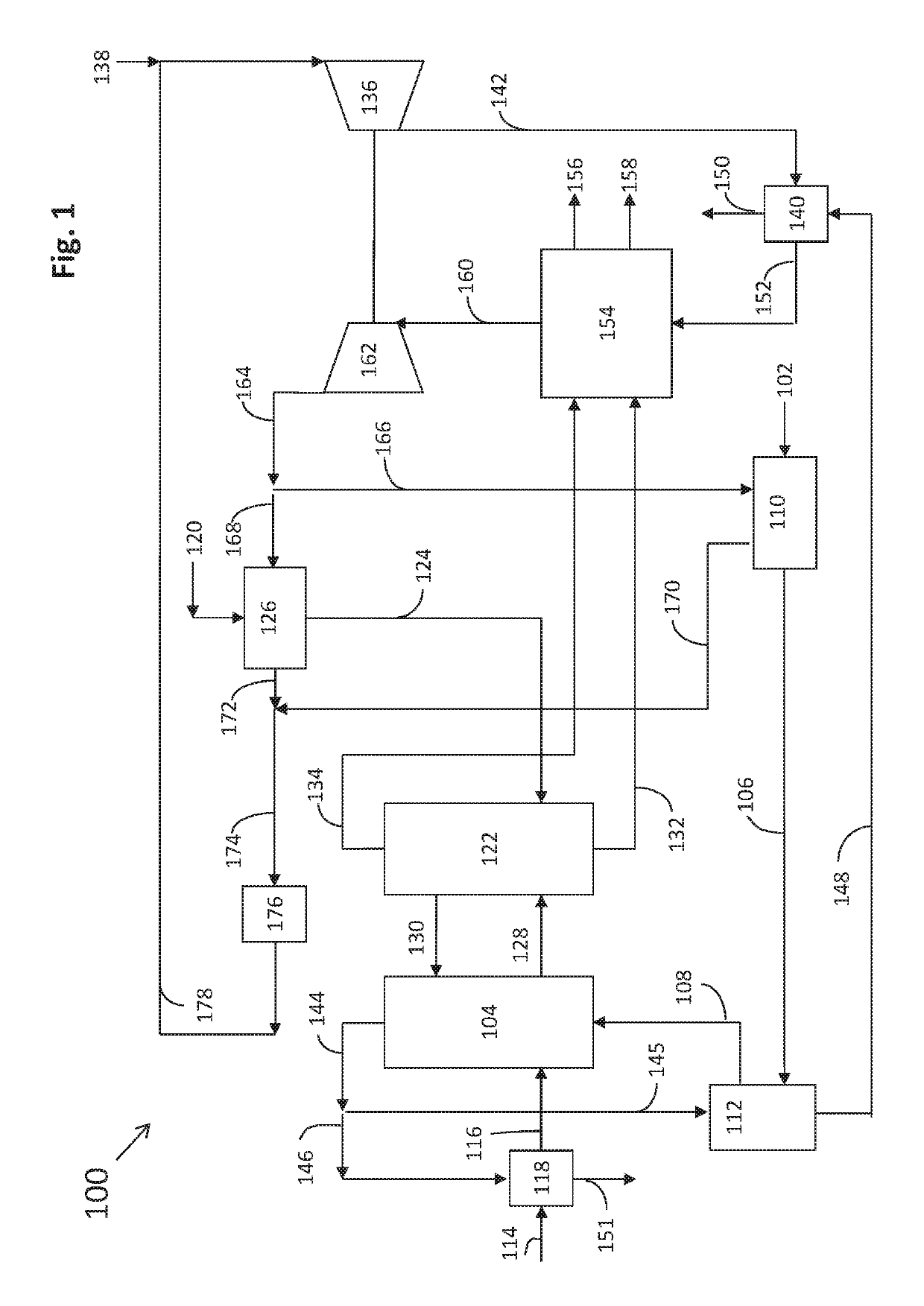
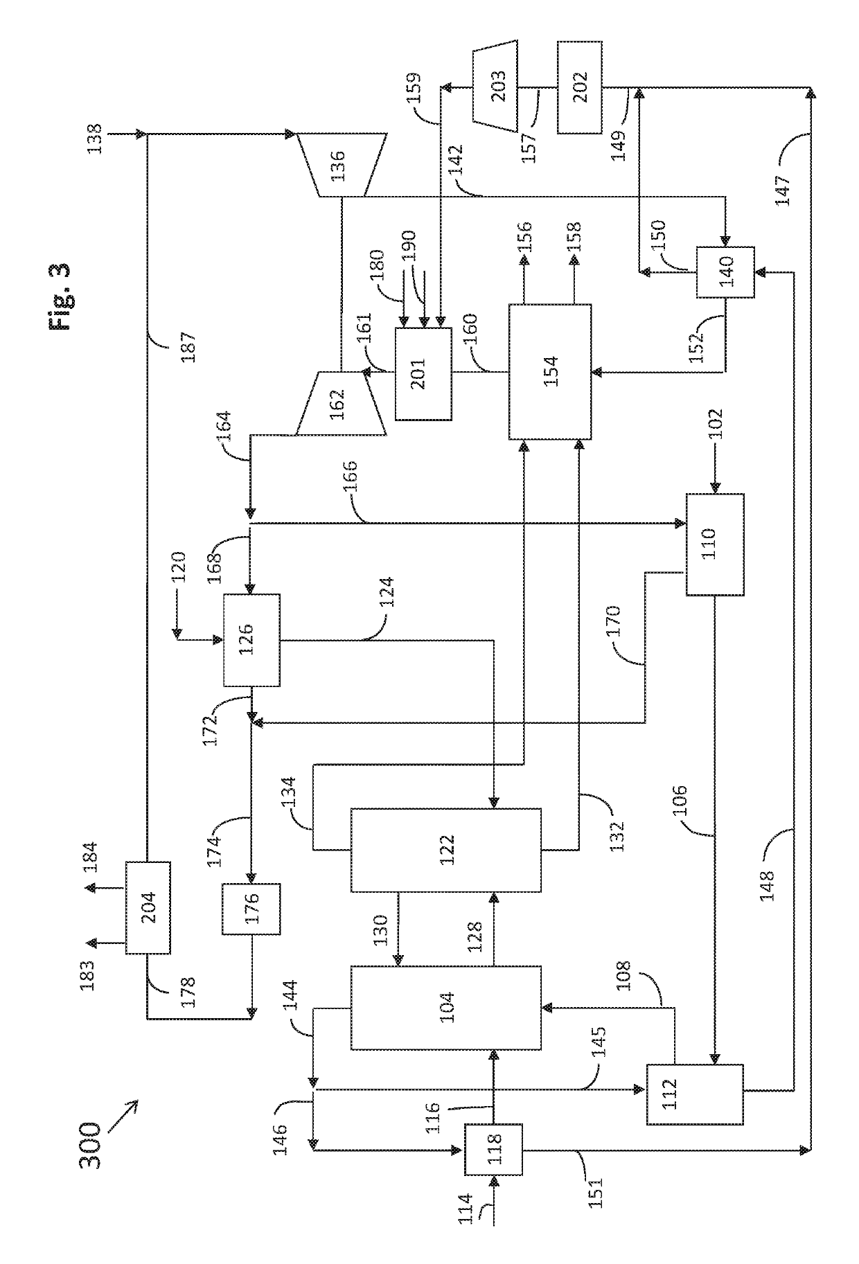
[0033]The present application describes systems and methods for coupling a chemical looping combustion arrangement and a supercritical CO2 cycle. The present application targets challenges regarding energy conversion efficiency and excessive water usage associated with conventional systems and provides solutions to such technical challenges among others.

[0034]In one or more embodiments, the system comprises a chemical looping combustion arrangement that comprises an air reactor and a fuel reactor. The fuel reactor receives fuel from a fuel source and receives oxygen carriers. The fuel reactor is configured to heat the received fuel and oxygen carriers. As a result, the fuel is oxidized (combusted) or reformed, resulting in combusted fuel or reformed fuel, respectively, as well as reduced oxygen carriers. The air reactor receives an air stream from an air source and the reduced oxygen carriers from the fuel reactor. The air reactor is configured to re-oxidize the reduced oxygen carri...


PUM


Abstract

Systems and methods for coupling a chemical looping arrangement and a supercritical CO2 cycle are provided. The system includes a fuel reactor, an air reactor, a compressor, first and second heat exchangers, and a turbine. The fuel reactor is configured to heat fuel and oxygen carriers resulting in reformed or combusted fuel and reduced oxygen carriers. The air reactor is configured to re-oxidize the reduced oxygen carriers via an air stream. The air stream, fuel, and oxygen carriers are heated via a series of preheaters prior to their entry into the air and fuel reactors. The compressor is configured to increase the pressure of a CO2 stream to create a supercritical CO2 stream. The first and second heat exchangers are configured to heat the supercritical CO2 stream, and the turbine is configured to expand the heated supercritical CO2 stream to generate power.

Description

TECHNICAL FIELD[0001]The present disclosure is related to systems and methods regarding supercritical CO2 cycles and chemical looping combustion. In particular, the present disclosure is related to systems and methods for coupling a supercritical CO2 cycle and a chemical looping combustion arrangement.BACKGROUND OF THE INVENTION[0002]As the need for energy continues to grow, so does the use of unconventional energy resources to meet the increasing demand. While well-known energy sources (e.g., coal, natural gas) continue to have value, other energy sources such as unconventional oil resources and unconventional natural gas resources are being used to meet the increasing energy demand. One such unconventional resource is sour gas, which is a natural gas that contains significant levels of hydrogen sulfide (H2S). H2S presents a problem during processing of the sour gas, as the corrosive nature of H2S can damage the mechanical parts of a system, and the processing of H2S can result in ...

Claims


Application Information

Patent Timeline
Patent Type & Authority Patents(United States)
IPC IPC(8): F01K25/10F23C10/18F23C10/26F01K7/32F23C10/01
CPCF01K25/103F23C10/18F01K7/32F23C10/01F23C10/26F23C2206/103F23C99/00F23C2900/99008F02C1/02F02C3/20F02C1/08F02C3/34Y02E20/34F02C1/10F02C1/05
Inventor YOUNES, MOURADHARALE, AADESHJAMAL, AQIL
Owner SAUDI ARABIAN OIL CO
Learn More