Thermal management using endothermic heat sink

a heat sink and endothermic technology, applied in the direction of cosmonautic vehicles, lighting and heating apparatus, heating types, etc., can solve the problems of large heat dissipation surfaces, low-grade heat from aircraft, and inability to easily integrate into airframes

Active Publication Date: 2020-03-03
THE UNITED STATES OF AMERICA AS REPRESETNED BY THE SEC OF THE AIR FORCE
View PDF38 Cites 6 Cited by
  • Summary
  • Abstract
  • Description
  • Claims
  • Application Information

AI Technical Summary

Benefits of technology

[0007]Another embodiment provides a method for managing heat transfer of a thermal load, the method comprising providing a thermal management system comprising a heat exchanger reactor containing an expendable heat absorption material; applying heat from a thermal load to the thermal management system at a temperature between approximately 18-30° C. using a thermal load coolant; transferring heat from the thermal load to a transfer fluid at a temperature above approximately 60° C. creating a heated transfer fluid, wherein the heated transfer fluid is introduced into the heat exchanger reactor; transferring heat from the heated transfer fluid into the expendable heat absorption material, wherein the expendable heat absorption material endothermically decomposes into a gaseous by-product; and maintaining the thermal load coolant within a specified temperature range independent of heat load dynamics.

Problems solved by technology

The dissipation of high-flux, low-grade heat from an aircraft presents unique challenges.
High-flux loads generally require large, high-capacity cooling systems.
Low-grade heat rejection typically requires large heat dissipation surfaces, which may not be readily integrated into airframes.
New composite materials which have low thermal conductivities are being used for airframes and present further thermal management challenges.
In addition, an aircraft's operating envelope may preclude dissipating low-grade heat to the atmosphere due to high aircraft skin and stagnation air temperatures during high-speed flight.
However, jet fuel may degrade in the presence of heat and dissolved O2 may form surface deposits and block fuel passages.
Furthermore, the available heat sink decreases in time as the jet fuel is consumed.
Thus, the use of jet fuel for thermal management is not without limitations, and alternative techniques to dissipate the heat are required.
Accordingly, the issue of managing low-quality waste heat onboard modern high-performance aircraft represents a critical performance limitation that can severely restrict flight envelopes, preclude the integration of high-power electronics, or compromise system reliability.

Method used


Image

  • Thermal management using endothermic heat sink
  • Thermal management using endothermic heat sink
  • Thermal management using endothermic heat sink

Examples


Embodiment Construction

[0022]Embodiments of the disclosed invention, its various features and the advantageous details thereof, are explained more fully with reference to the non-limiting embodiments that are illustrated in the accompanying drawings and detailed in the following description. Descriptions of well-known components and processing techniques are omitted to not unnecessarily obscure what is being disclosed. Examples may be provided and when so provided are intended merely to facilitate an understanding of the ways in which the invention may be practiced and to further enable those of skill in the art to practice its various embodiments. Accordingly, examples should not be construed as limiting the scope of what is disclosed and otherwise claimed.

[0023]In the drawings, the size and relative sizes of layers and regions may be exaggerated for clarity. The principal engineering challenges to the thermal systems engineer are the large quantities of heat involved, low (and carefully controlled) cool...


PUM


Abstract

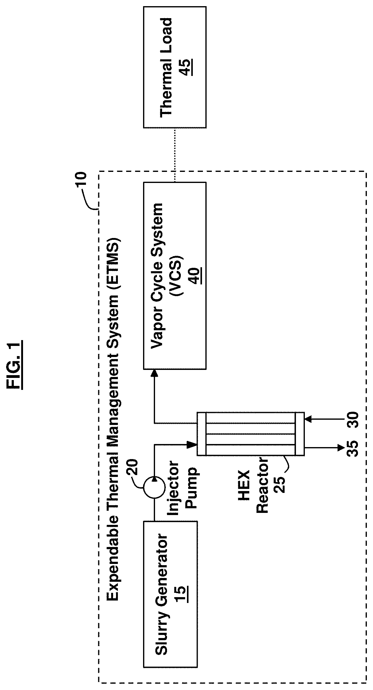
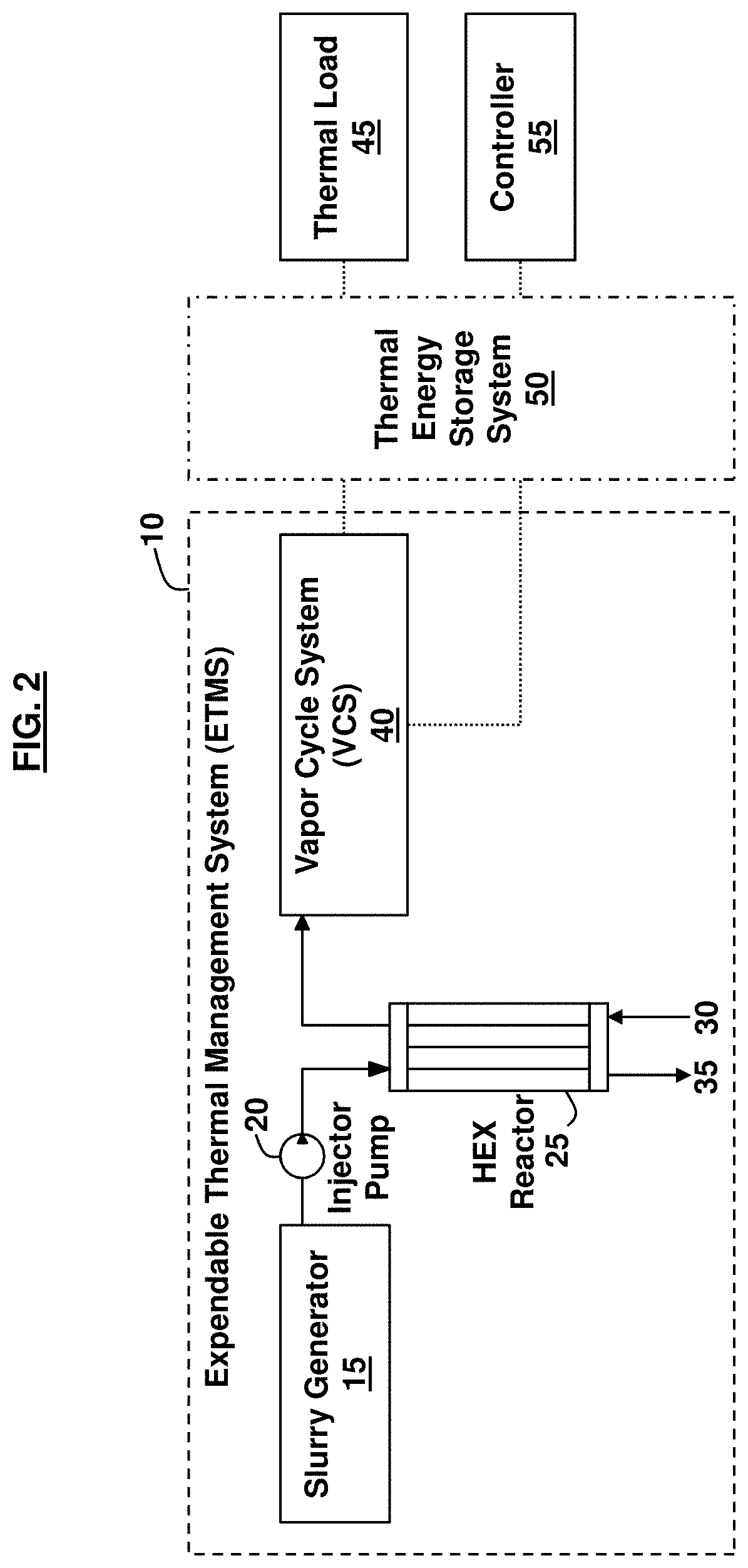
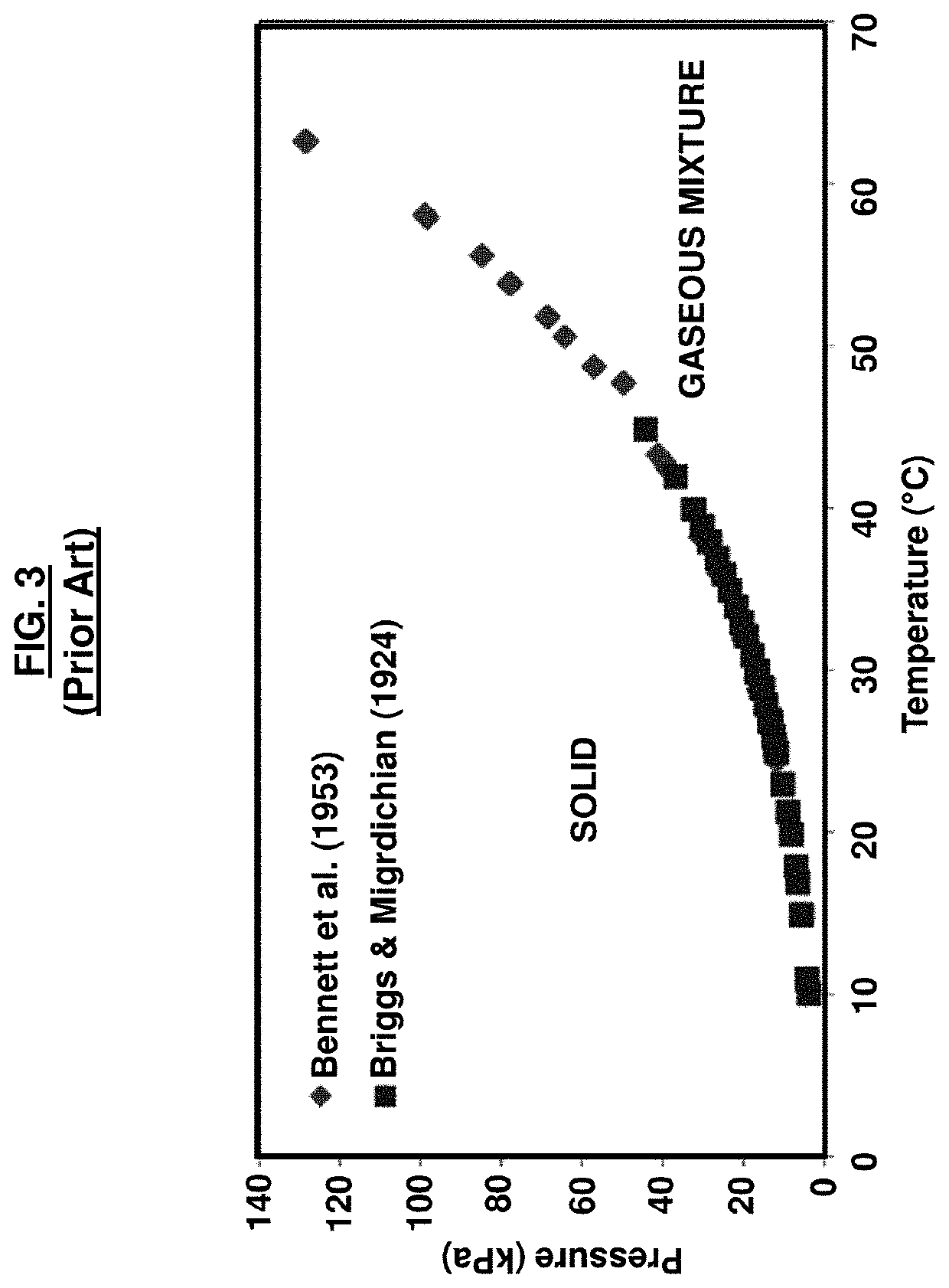
A thermal management system includes a slurry generator, an injector pump coupled to the slurry generator, a heat exchanger reactor coupled to the injector pump, wherein the heat exchanger reactor is adapted to subject a thermally expendable heat absorption material to a temperature above 60° C. and a pressure below 3 kPa, and wherein the expendable heat absorption material endothermically decomposes into a gaseous by-product. A vapor cycle system is coupled to the heat exchanger reactor and is operatively connected to a thermal load. A thermal energy storage system may be coupled to the vapor cycle system and the thermal load. The thermal energy storage system may isolate the heat exchanger reactor from thermal load transients of the thermal load.

Description

GOVERNMENT INTEREST[0001]The invention described herein may be manufactured and used by or for the Government of the United States for all government purposes without the payment of any royalty.BACKGROUNDField of the Invention[0002]The embodiments herein generally relate to thermal management systems, and more particularly to using ammonium carbamate for thermal management systems.Background of the Invention[0003]High-performance aircraft are experiencing increased use of high-power electronics. Many of these electronic systems produce high-flux, low-grade heat that must be removed to avoid component failure. The dissipation of high-flux, low-grade heat from an aircraft presents unique challenges. High-flux loads generally require large, high-capacity cooling systems. Low-grade heat rejection typically requires large heat dissipation surfaces, which may not be readily integrated into airframes. New composite materials which have low thermal conductivities are being used for airframe...

Claims


Application Information

Patent Timeline
Patent Type & Authority Patents(United States)
IPC IPC(8): F24D11/00F28D20/00F28D20/02B64G1/42F28D15/02F28D15/06F28D21/00
CPCF28D15/06F28D20/003F28D20/02B64G1/423F28D15/0266F28D2021/0022F28D2021/0021F28D2021/0029F28F23/00C09K5/16Y02E60/14B64D47/00B64D2221/00
Inventor JOHNSON, DOUGLAS J.NIEDBALSKI, NICHOLAS P.ERVIN, JAMIE S.PATNAIK, SOUMYA S.
Owner THE UNITED STATES OF AMERICA AS REPRESETNED BY THE SEC OF THE AIR FORCE
Why Eureka
Try Eureka