Near-eye foveal display

a display and near-eye technology, applied in the field of display systems, can solve problems such as cumbersomeness and bulkiness, and achieve the effect of rapid frame rate and high resolution

Active Publication Date: 2020-03-10
SOLIDDD
View PDF3 Cites 0 Cited by
  • Summary
  • Abstract
  • Description
  • Claims
  • Application Information

AI Technical Summary

Benefits of technology

[0008]In accordance with the present invention, a method and system uses a plurality of light-emitting devices behind a plurality of light-directing beads or microlenses in relation to a user's eye. The device is called a foveal display because it focuses light directly and precisely into the fovea of the viewer's eyes. The device replaces the typical optics in a bulky and cumbersome virtual reality (VR) headset. The device, or foveal display, allows for high resolution display in a lightweight device that gives the user a wide-angle view and rapid frame rate.
[0010]A processor controls the focus of the device. The focus may be adjusted based upon user preferences. Alternatively, the processor can automatically change the focus. The device may be deployed either in a large panel or in a near-eye display in either a flat panel or curved display that follows the curvature of the eye. The present device offers advantages to the use of traditional near-eye displays due to lightweight construction, high resolution, fast frame rate, extremely wide field of view, and reduced need for a secondary display device. In a flat panel display, the present device offers advantages in showing an extremely wide field of view for autostereo 3-dimensional (3D) display.

Problems solved by technology

The device replaces the typical optics in a bulky and cumbersome virtual reality (VR) headset.

Method used


Image

  • Near-eye foveal display
  • Near-eye foveal display
  • Near-eye foveal display

Examples


Embodiment Construction

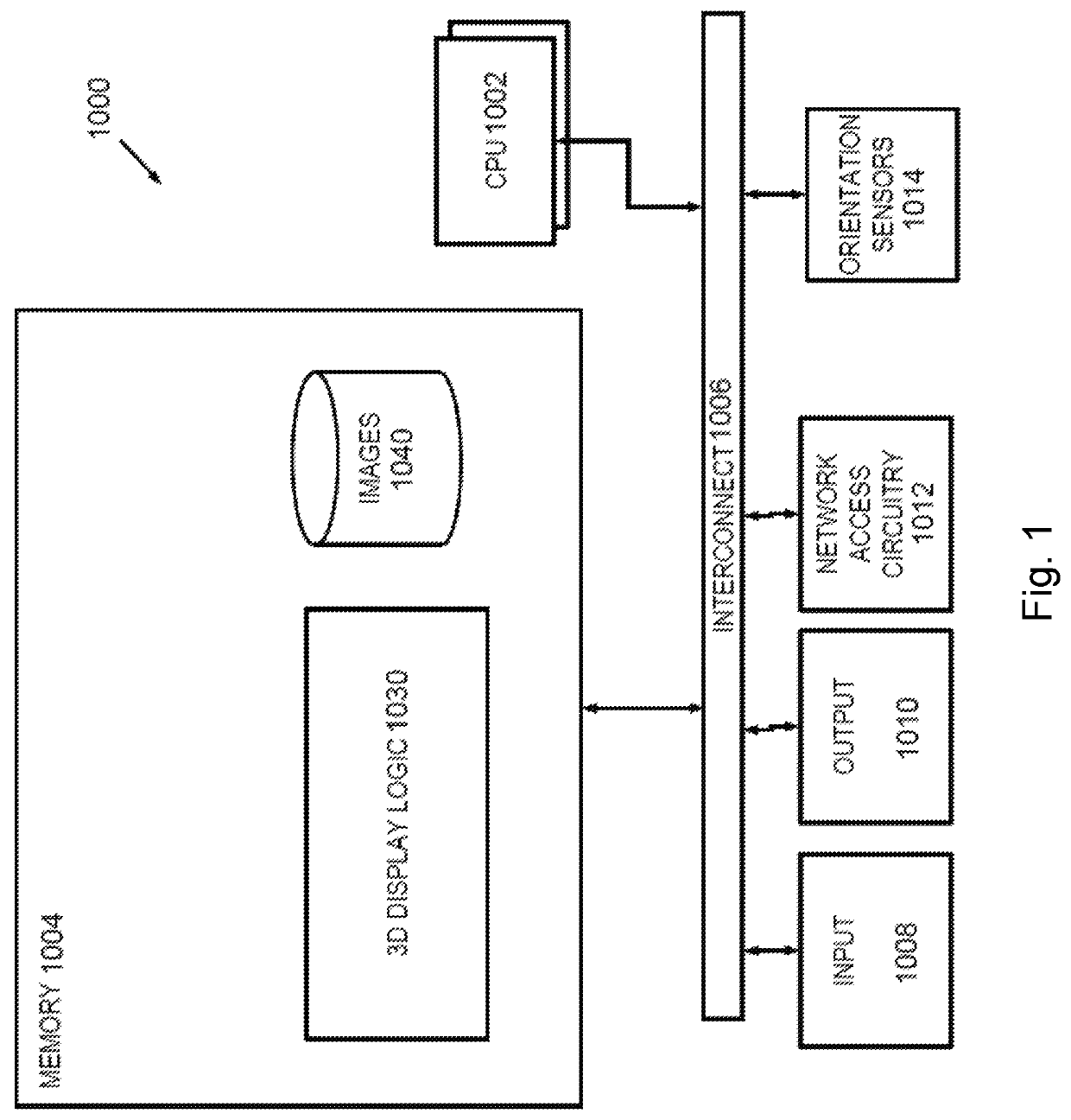
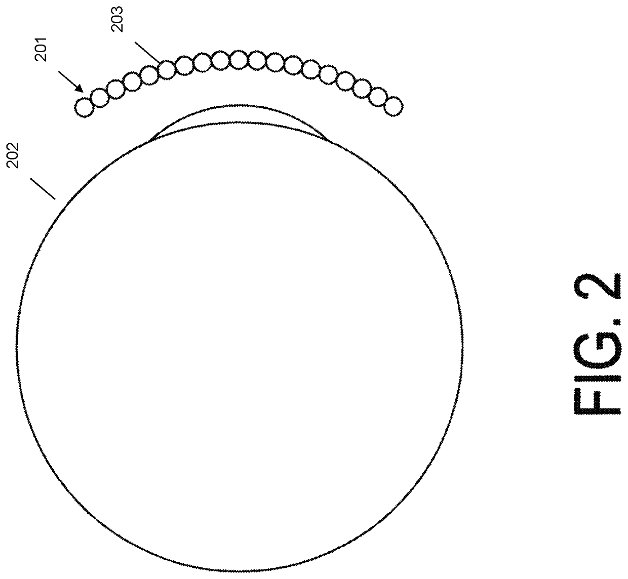
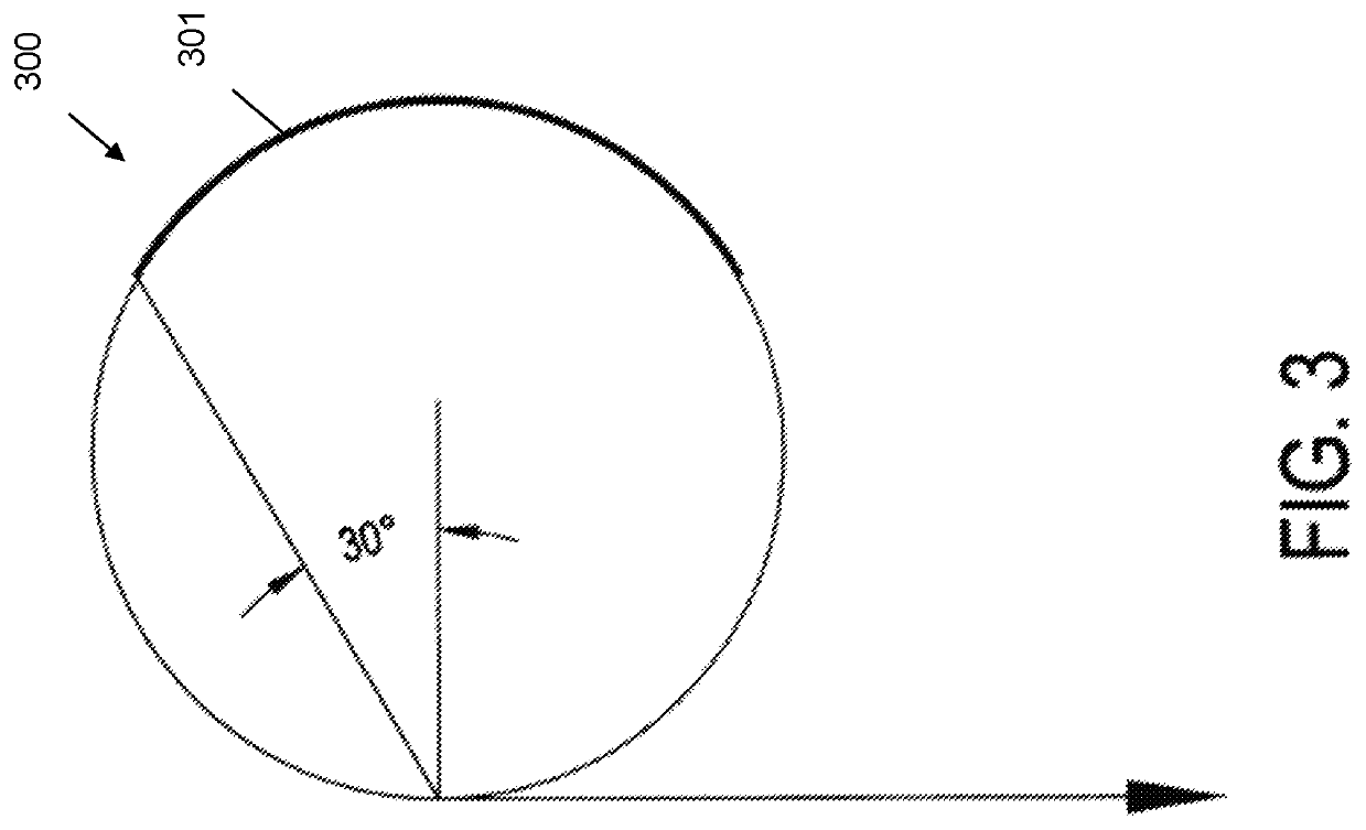
[0017]In accordance with the present invention, an embodiment provides a method and system of providing a high-resolution near-eye display. The system provides for a near-eye display without the large and cumbersome headsets found in conventional virtual reality headsets. The apparatus comprises a plurality of light-directing beads or microlenses. Reference in this application to the light-directing lenses may also be called light-directing beads or beads for brevity and ease of reading. The bead's shape may include fish-eye, spherical, ovoid, hexagonal, square, columnar, triangular, or like 3-dimensional shapes or like cross dimensional shapes. The term bead should not be construed as referring only to a spherical structure, although spherical beads may be an embodiment. Bead shapes in figures are illustrative only of an embodiment. Each of the disclosed beads shapes may have a different refractive index in different embodiments. The lenses are arranged in a pattern having a first ...


PUM


Abstract

An apparatus and system for a display screen for use in near-eye display devices. Small light emitting devices are placed behind a plurality of light-directing beads. The light emitting devices and light-directing beads for a display device and system placed in front of a user for near-eye display. This allows a user to experience near-eye display with greater resolution, wider field of view and faster frame rate. Other embodiments are described herein.

Description

CROSS-REFERENCE TO RELATED APPLICATIONS[0001]This application is a continuation-in-part of U.S. application Ser. No. 15 / 594,029, filed May 12, 2017, the contents of which are incorporated by reference herein.FIELD OF THE INVENTION[0002]The present invention relates generally to display systems, and, more particularly, to display systems for near-eye displays such as virtual reality and augmented reality.BACKGROUND OF THE INVENTION[0003]Recently, there has been significant growth in the use and advancement of virtual reality, augmented reality, and similar near-eye products. Common virtual reality uses include video gaming, movies, amusement ride simulators, and the like. While the popularity is driven by entertainment, the products also serve functions in training and education. For example, virtual reality headsets may be used for flight simulation training, surgery simulation for physicians, technology in the traditional classroom to spark student interest in a subject, and the li...

Claims


Application Information

Patent Timeline
Patent Type & Authority Patents(United States)
IPC IPC(8): G02B3/00G02B27/01
CPCG02B3/0056G02B27/0172G02B2003/0093
Inventor MULLER, RICHARD A.WEINSTOCK, NEAL
Owner SOLIDDD
Why Eureka
Try Eureka