Cutting tool

a cutting tool and tool body technology, applied in the field of cutting tools, can solve the problems of short working life, poor machined surface quality, low material removal rate of conventional cutting tools, etc., and achieve the effect of making the cutting tool more robust and useful to the user

Active Publication Date: 2020-04-14
ROLLS ROYCE PLC
View PDF32 Cites 0 Cited by
  • Summary
  • Abstract
  • Description
  • Claims
  • Application Information

AI Technical Summary

Benefits of technology

[0014]The cutting tool geometry having abrasive particles on the flank face provides two additional abrasive zones (cutting zones) in addition to the main defined cutting edges. Increasing the quantity of effective cutting zones reduces cutting forces per cutting edge or region, and extends the cutting edge life over conventional cutting tools in which the cutting lips are the only cutting edges
[0060]For small diameter cutting tools, forming the abrasive features by ablating the flank surface to leave the abrasive features standing proud of the flank surface results in a finished cutting tool in which the abrasive features are an integral with the cutting tool. This makes the cutting tool more robust and useful to a user.

Problems solved by technology

The heterogenic, anisotropic and high hardness properties of these CMC materials means that conventional cutting tools have low material removal rates, a short working life and poor machined surface quality.
Conventional cutting tools experience high wear rates, particularly when the cutting force is dynamically varying through the cut (as is the case for CMC materials).
Therefore the cutting edge geometry is rapidly changed, so decreasing significantly the resulting surface quality.

Method used


Image

  • Cutting tool
  • Cutting tool
  • Cutting tool

Examples


Embodiment Construction

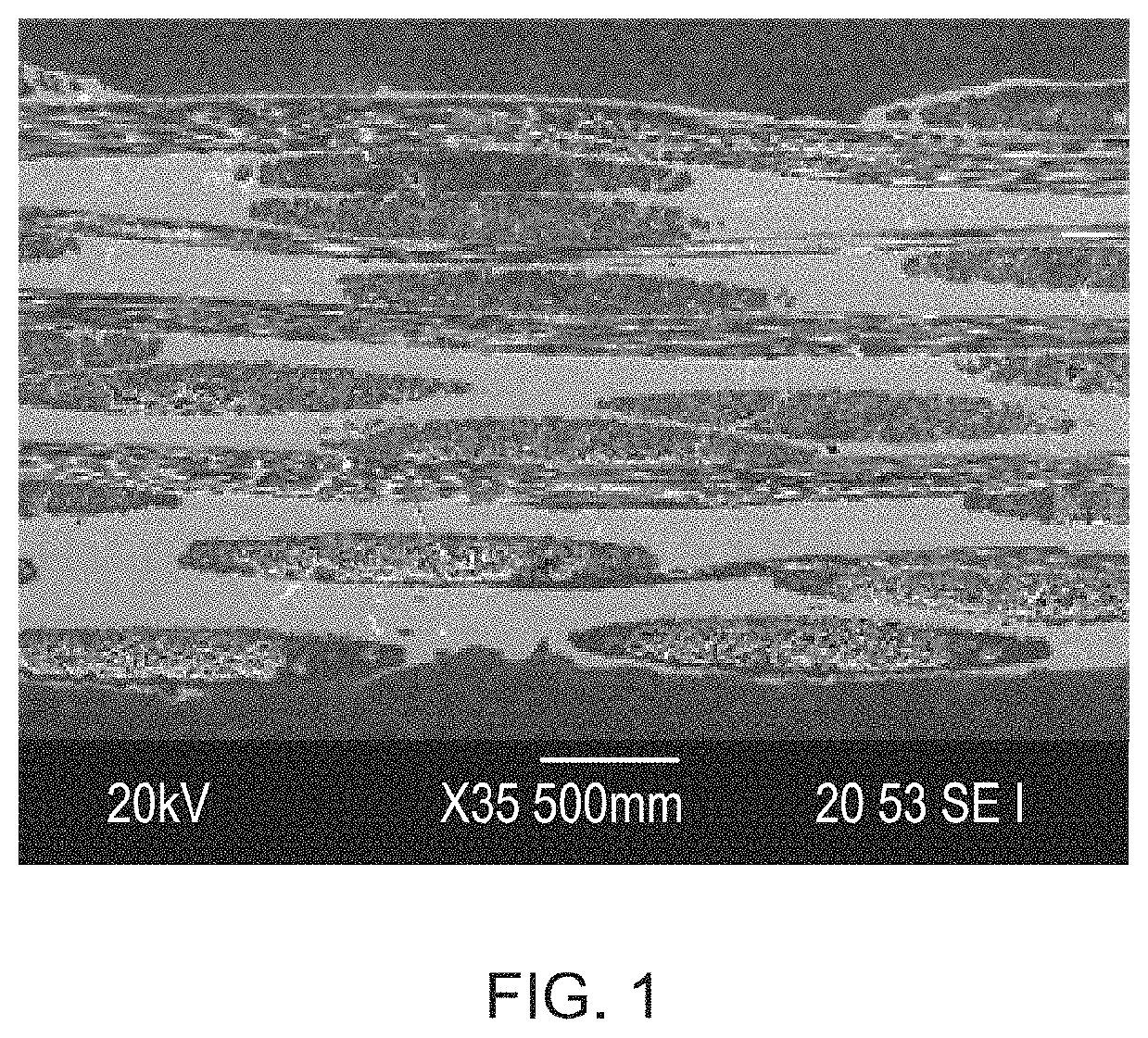
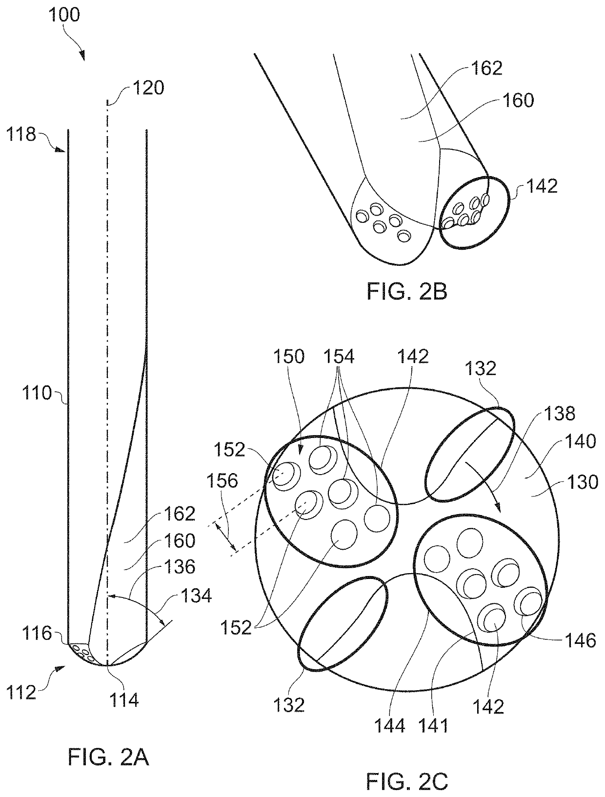
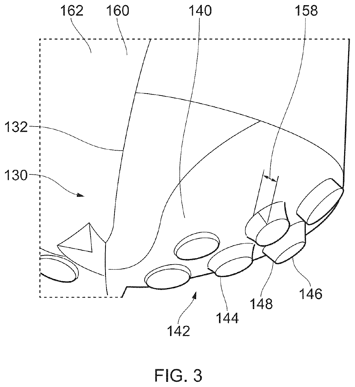
[0075]Referring to FIGS. 2 and 3, a cutting tool according to an embodiment of the disclosure is designated generally by the reference numeral 100.

[0076]The cutting tool 100 comprises a tool body 110 having a first end 112 and an opposite second end 114. In the present embodiment, the tool body 110 has a generally cylindrical geometry. In other embodiments, the tool body 110 may have an alternative elongate geometry. The tool body 110 has a longitudinal axis 120.

[0077]In the present embodiment the second end 114 corresponds to a shank or holding portion (not shown) which would be used to hold the cutting tool 100 in a machine tool (not shown).

[0078]The first end 112 of the tool body 110 has a centre region 114 and a perimetral edge 116. The centre region 114 of the first end 112 corresponds to the intersection of the longitudinal axis 120 with the first end 112. The perimetral edge 116 of the first end 112 corresponds to the circumferential edge of the first end 112 of the first end...


PUM

PropertyMeasurementUnit
heightaaaaaaaaaa
abrasiveaaaaaaaaaa
angleaaaaaaaaaa

Abstract

A cutting tool comprises a tool body having a first end and a second end, and a longitudinal axis extending between the first end and the second end. The first end comprises two or more cutting portions, with each of the cutting portions comprising a cutting edge and a flank surface.Each cutting edge extends radially outwardly from a centre region of the first end to a perimetral edge of the first end, with the cutting edge being angled relative to the longitudinal axis. Each flank surface extends circumferentially from the cutting edge.Each of at least two of the two or more flank surfaces comprises an abrasive portion extending over at least a part of the respective flank surface and each abrasive portion comprises a plurality of abrasive features.

Description

CROSS-REFERENCE TO RELATED APPLICATIONS[0001]This disclosure claims the benefit of UK Patent Application No. GB 1706687.9, filed on 27 Apr. 2017, which is hereby incorporated herein in its entirety.FIELD OF THE DISCLOSURE[0002]The present disclosure relates to a cutting tool having abrasive features and particularly, but not exclusively, to a drill having abrasive features.BACKGROUND TO THE DISCLOSURE[0003]Ceramic Matric Composite (CMC) materials are formed from ceramic fibres 10 reinforcing a ceramic matrix an example being shown in FIG. 1. CMC materials have excellent high temperature mechanical properties. CMC materials are currently being considered to replace high temperature metal alloys (such as nickel based superalloys) in applications such as gas turbine engine segments, vanes and blades, and also in combustor heat shields.[0004]CMC materials need machining processes such as grinding, drilling or milling to achieve the final shape of the workpiece. Conventional drilling cut...

Claims


Application Information

Patent Timeline
Patent Type & Authority Patents(United States)
IPC IPC(8): B23B51/02B23B51/08B23B51/04B23P15/32B23P15/28B28D1/14
CPCB23B51/08B23B51/02B23B51/0406Y10T408/81B23B2200/123B23P15/32B23B2200/28B23B2228/12B23B2226/125B28D1/146B23B2200/204B23B2226/31Y10T408/353B23B2200/245B23B2251/285B23P15/28B23B51/04
Inventor NOVOVIC, DONKAGAVALDA DIAZ, ORIOLAXINTE, DRAGOS A.BUTLER-SMITH, PAUL
Owner ROLLS ROYCE PLC
Why Eureka
Try Eureka