
Phase transition suppression heat transfer plate-based heat exchanger

a heat exchanger and phase transition technology, applied in the field of phase transition suppression heat transfer plate type heat exchangers, can solve the problems of increasing the weight and volume of the heat exchanger, increasing the power consumption of liquid circulation, and the efficiency of the fin is relatively low, so as to improve the heat equalization performance. , the effect of high heat conduction efficiency of the phase change suppression heat exchange devi

Active Publication Date: 2020-04-14
ZHEJIANG JIAXI TECH CO LTD
View PDF7 Cites 0 Cited by
  • Summary
  • Abstract
  • Description
  • Claims
  • Application Information

AI Technical Summary

Benefits of technology

The present invention provides a phase change suppression heat transfer plate-type heat exchanger that solves problems in the prior art by reducing the length of the liquid pipeline, flowing resistance, and improves heat exchange efficiency. The heat exchanger has a closed network-shaped pipeline filled with a phase change suppression working medium that improves temperature equalization and increases heat dissipation capability. The efficient heat exchange between the phase change suppression heat transfer device and the air improves heat dissipation and exchange efficiency. This results in a heat exchanger with improved efficiency and energy efficiency ratio.

Problems solved by technology

Since the liquid pipeline is connected in series, the pipeline is long, the flowing resistance is large, there is contact heat resistance between the fin outside the pipeline and the liquid pipeline, the heat conduction coefficient of the employed heat sink is 200 W / m.k, the efficiency of the fin is relatively low, and the dimension of the fin is relatively small, the length of the liquid pipeline and the number of fins need to be increased to meet the heat dissipation demand, which also increase the weight and volume of the heat exchanger and at the same time increases the power consumption of liquid circulation, increasing system costs, volume and weight.

Method used


Image

  • Phase transition suppression heat transfer plate-based heat exchanger
  • Phase transition suppression heat transfer plate-based heat exchanger
  • Phase transition suppression heat transfer plate-based heat exchanger

Examples


embodiment 1

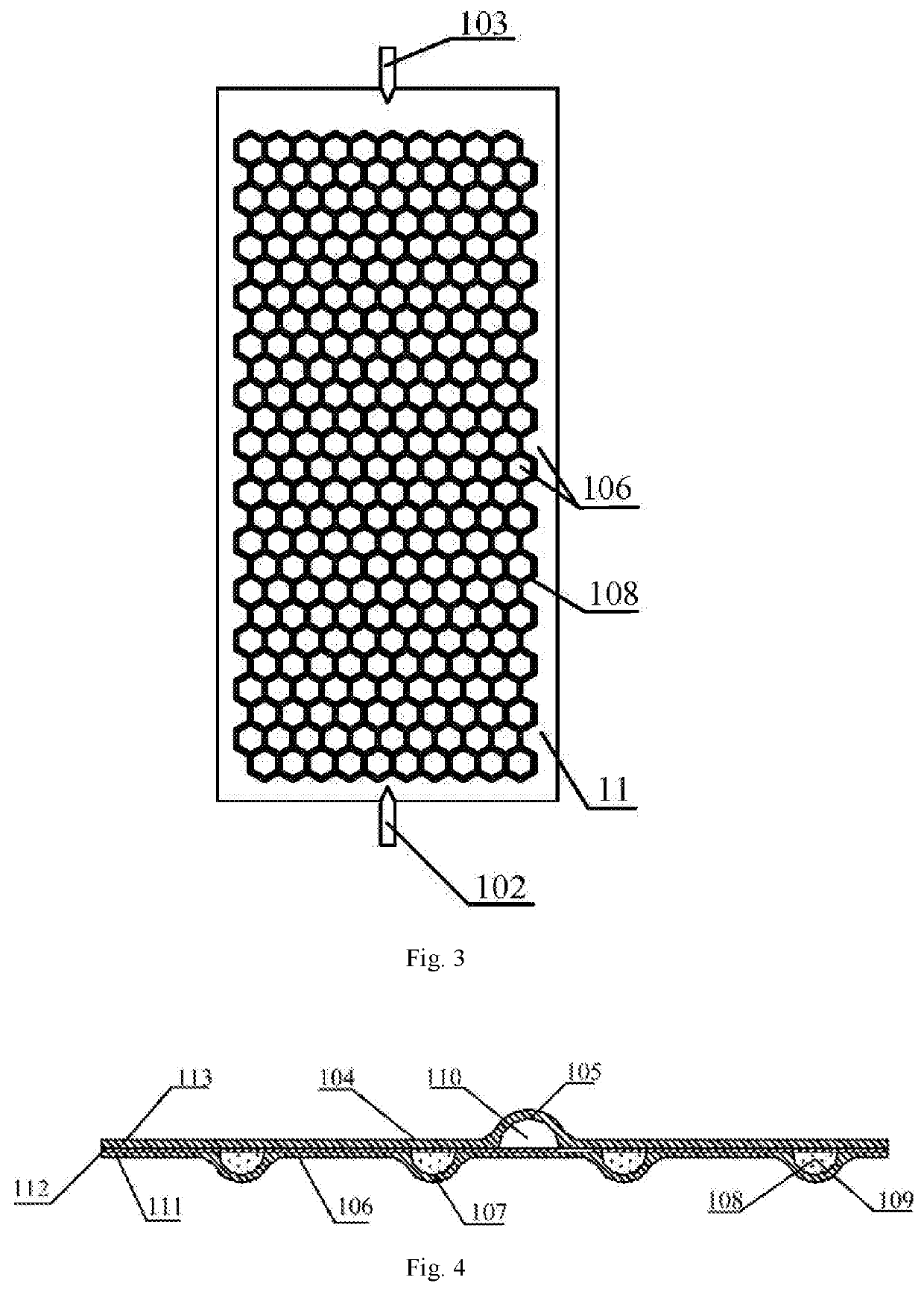
[0061]Referring to FIGS. 1 to 4, the present invention provides a phase change suppression heat transfer plate-type heat exchanger, including: an inlet communication header pipe 2, an outlet communication header pipe 3 and a plurality of phase change suppression heat transfer heat exchange plates 11 arranged in parallel; the surfaces of the phase change suppression heat transfer heat exchange plates 11 are parallel to each other, the phase change suppression heat transfer heat exchange plate 11 is a composite plate structure, the phase change suppression heat transfer heat exchange plates 11 is provided with a liquid pipeline 110 of a certain structure shape and a closed network-shaped pipeline 108 of a certain structure shape, wherein the closed network-shaped pipeline 108 is filled with a phase change suppression working medium 109; the inlet communication header pipe 2 and the outlet communication header pipe 3 are at least fixed at one side of the phase change suppression heat t...

embodiment 2

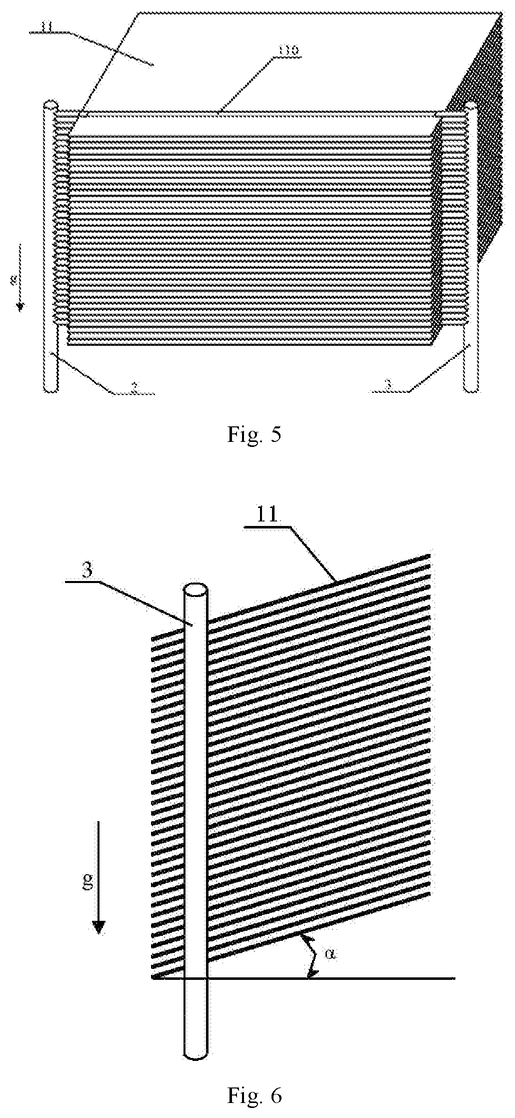
[0076]Referring to FIGS. 5 to 9, the present invention also provides a phase change suppression heat transfer plate-type heat exchanger. The structure of the phase change suppression heat transfer plate-type heat exchanger in this embodiment is substantially the same as that of the phase change suppression heat transfer plate-type heat exchanger in embodiment I. The differences lie in that: the distribution location of the liquid pipeline 110 on the surface of the phase change suppression heat transfer heat exchange plate 11 is different; the angles between the surface of the phase change suppression heat transfer heat exchange plate 11 and the inlet communication header pipe 2 and the outlet communication header pipe 3 are different; and the installation direction of the phase change suppression heat transfer plate-type heat exchanger during actual application is different.

[0077]In particular, in embodiment I, the liquid pipeline 110 is preferably located on the longitudinal centra...

embodiment 3

[0082]Referring to FIGS. 10 to 11, the present invention also provides a phase change suppression heat transfer plate-type heat exchanger. The structure of the phase change suppression heat transfer plate-type heat exchanger in this embodiment is substantially the same as that of the phase change suppression heat transfer plate-type heat exchanger in embodiment I. The differences lies in that: the distribution location of the liquid pipeline 110 on the surface of the phase change suppression heat transfer heat exchange plate 11 is different; and the installation direction of the phase change suppression heat transfer plate-type heat exchanger during actual application is different.

[0083]In particular, in embodiment I, the liquid pipeline 110 is preferably located on the longitudinal central line of the phase change suppression heat transfer heat exchange plate 11. However, in this embodiment, as shown in FIG. 7, the liquid pipeline 110 is close to one side of the phase change suppre...


PUM


Abstract

A phase change suppression heat transfer plate-type heat exchanger comprises an inlet communication header pipe, an outlet communication header pipe and a plurality of phase change suppression heat transfer heat exchange plates arranged in parallel. The phase change suppression heat transfer heat exchange plate is provided with a liquid pipeline of a certain structure shape and a closed network-shaped pipeline of a certain structure shape. The closed network-shaped pipeline is filled with a phase change suppression working medium. The inlet communication header pipe and the outlet communication header pipe are at least fixed at one side of the phase change suppression heat transfer heat exchange plate. The lengthwise directions of the inlet communication header pipe and the outlet communication header pipe extend along the parallel arrangement direction of the plurality of phase change suppression heat transfer heat exchange plates.

Description

CROSS REFERENCE TO RELATED PATENT APPLICATION[0001]The present application is the US national stage of PCT / CN2016 / 082585 filed on May 19, 2016, which claims the priority of the CN2015104778350 filed on Aug. 6, 2015, which application is incorporated herein by reference.BACKGROUND OF THE PRESENT INVENTION[0002]Field of Invention[0003]The present invention relates to a heat exchanger, and in particular relates to a phase change suppression heat transfer plate-type heat exchanger.[0004]Description of Related Arts[0005]Gas-liquid heat exchangers are widely applied in the fields such as automobile heat sinks, evaporator and condenser of air conditioners, liquid cooling system of High-speed Railway traction system converters, wind-electricity converter cooling systems, data centers and so on. With the rapid development of technology, the requirements to the heat exchangers are higher and higher, which not only requires high heat exchange efficiency, small volume and light weight but also ...

Claims


Application Information

Patent Timeline
Patent Type & Authority Patents(United States)
IPC IPC(8): F28F23/02F28D1/03F28F3/14F28D15/02
CPCF28D15/0233F28F23/02F28D1/0316F28F3/14
Inventor TONG, AIXINGLI, JUQIANG
Owner ZHEJIANG JIAXI TECH CO LTD
Learn More