High-speed grooving method

a high-speed grooving and groove technology, applied in the field of grooves, can solve the problems of time-consuming, slow carriage movement speed, and long time-consuming to machine all longitudinal grooves on the entire surface of the roll, and achieve the effect of efficient machined

Active Publication Date: 2020-06-09
TOSHIBA MASCH CO LTD
View PDF14 Cites 0 Cited by
  • Summary
  • Abstract
  • Description
  • Claims
  • Application Information

AI Technical Summary

Benefits of technology

[0007]In the case of machining circumferential grooves in a roll by using an ultra-precision roll turning lathe, each groove can be machined by allowing a diamond tool to cut in the rotating roll in the X-axis direction. The next groove can be machined after moving a carriage a distance equal to the pitch of the grooves. In this manner, the grooves can be efficiently machined.
[0012]The present invention has been made in view of the above problems in the prior art. It is therefore an object of the present invention to provide a high-speed grooving method which, when machining fine grooves in the surface of a workpiece by using an ultra-precision roll turning lathe or a planer machine, can machine each groove not only during a forward stroke of a cutting tool but also during a return stroke of the cutting tool, and can therefore significantly increase the machining efficiency.

Problems solved by technology

It takes a long time to machine all the longitudinal grooves in the entire surface of the roll for the following reasons.
Firstly, the movement speed of the carriage is as slow as about 10 to 20 meters / minute; therefore, it takes time even to feed the carriage from one end to the other end of the roll, e.g. having a length of about 2 meters, in the longitudinal direction of the roll.
Therefore, after machining a groove with a diamond tool during a forward stroke, the groove cannot be further machined during a return stroke because the rake face of the diamond tool faces in the opposite direction to the movement direction, i.e. the cutting direction, of the diamond tool.

Method used


Image

  • High-speed grooving method
  • High-speed grooving method
  • High-speed grooving method

Examples


first embodiment

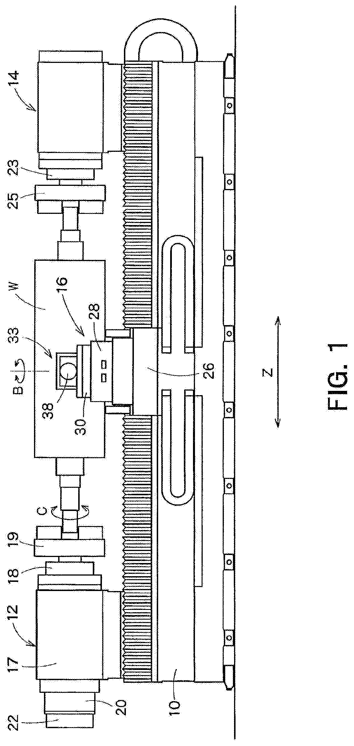
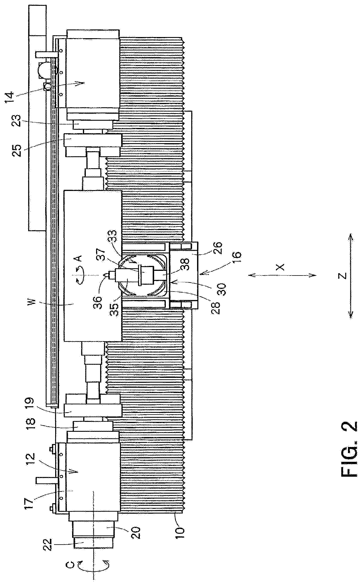
[0025]FIG. 1 is a side view of a precision roll turning lathe for performing a high-speed grooving method according to a first embodiment of the present invention, and FIG. 2 is a plan view of the precision roll turning lathe.

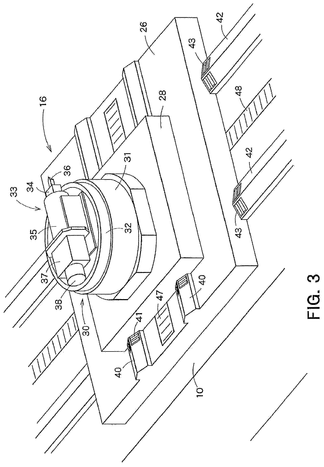
[0026]In FIGS. 1 and 2, reference numeral 10 denotes a bed. On the bed 10 are mounted a headstock 12, a tail stock 14 and a carriage 16. A roll W as a workpiece is rotatably supported by the headstock 12 and the tail stock 14.

[0027]The headstock 12 is disposed on one longitudinal end of the bed 10. The headstock 12 includes a body 17, a main spindle 18, a chuck 19 secured to the front end of the main spindle 18, and a servo motor 20 for driving the main spindle 18. The main spindle 18 is supported by a not-shown hydrostatic oil bearing provided within the body 17. The chuck 19 holds a one-end spindle of the roll W and transmits the rotation of the main spindle 18 to the roll W. In the headstock 12, the servo motor 20 drives the main spindle 18 to rotate the rol...

second embodiment

[0066]A high-speed grooving method according to a second embodiment of the present invention will now be described with reference to FIGS. 9 and 10. The second embodiment is suitable in cases where the displacement of a cutting tool cannot be completely corrected by the grooving method of the first embodiment. In some cases, even when dummy machining is performed by reciprocating the diamond tool 36 and a groove, formed in the surface of the roll W, is observed with a digital microscope (optical microscope) to measure a displacement δ as shown in FIG. 6, the error cannot be completely eliminated based on the measurement results.

[0067]FIGS. 9A through 9F illustrate an exemplary process for machining fine lateral longitudinal grooves in the surface of the roll W by performing the high-speed grooving method of the second embodiment.

[0068]In the second embodiment, in order to machine a single lateral groove, the diamond tool 36 is reciprocated two and a half times from end to end of the...


PUM

PropertyMeasurementUnit
depthaaaaaaaaaa
depthaaaaaaaaaa
lengthaaaaaaaaaa

Abstract

A method for machining grooves in the surface of a workpiece in which a dummy groove is machined in the surface of the workpiece by moving a cutting tool relative to the workpiece in a first machining direction of the workpiece, then orienting the cutting tool 180 degrees as compared to the first machining, and subsequently second machining the dummy groove by moving the cutting tool in a second direction opposite to the first direction. A displacement of a cutting edge of the cutting tool, caused by the first and second machining of the dummy groove is measured. A groove is machined with the cutting tool in a forward stroke and then a return stoke with the cutting tool rotated 180 degrees between the strokes. A relative position between the workpiece and the cutting tool during the forward and return strokes is corrected so as to eliminate the displacement.

Description

CROSS REFERENCE TO RELATED APPLICATIONS[0001]This application is a U.S. Non-Provisional Application, which claims priority from Japanese Patent Application No. JP 2017-165719 filed Aug. 30, 2017. The entirety of the above-listed application is incorporated herein by reference.TECHNICAL FIELD[0002]The present invention relates to a grooving method for machining fine grooves in a workpiece at a high speed.BACKGROUND ART[0003]Ultra-precision roll turning lathes have recently been developed which achieve ultra-precision machining of a roll for molding a lenticular lens sheet, a cross lenticular lens sheet, a prism sheet, or the like (see, for example, patent document 1).[0004]Such an ultra-precision roll turning lathe includes a tool post having a diamond tool attached thereto, installed on a carriage, and is basically used to machine circumferential grooves in a roll while rotating the roll by means of a headstock and feeding the carriage in a forward-backward direction (X-axis directi...

Claims


Application Information

Patent Timeline
Patent Type & Authority Patents(United States)
IPC IPC(8): B23B5/08B23B21/00B23D11/00
CPCB23D11/00B23B5/08B23B2220/12B23B2226/31B23C2226/31B23B25/06B23B29/12B23Q17/20B23D1/18B23B2260/004B23Q2717/003B23B2270/48
Inventor AKIYAMA, TAKANOBU
Owner TOSHIBA MASCH CO LTD
Why Eureka
Try Eureka