Gas fuel burner and method for heating with gas fuel burner

a gas fuel burner and burner technology, applied in the direction of burners, combustion types, combustion processes, etc., can solve the problems of not being suited to heating, unable to raise the flow speed of the flame, and unable to achieve the effect of heating, suppressing the oxidation of the object, and high axial flame speed

Active Publication Date: 2020-06-09
NIPPON SANSO CORP
View PDF20 Cites 0 Cited by
  • Summary
  • Abstract
  • Description
  • Claims
  • Application Information

AI Technical Summary

Benefits of technology

[0031]The present invention allows a high axial flame speed and a high temperature flame without losing combustion efficiency and can suppress oxidation of the object to be heated and improve convection heat transfer efficiency.

Problems solved by technology

For this reason, when the discharge speed of the oxygen and / or the gas fuel is raised with the aim of increasing the flow speed of the flame, since blow-off of the flame occurs, it is not possible to raise the flow speed of the flame.
Since the oxygen concentration thereby increases when impinged on an object to be heated, in the case of heating a material that easily oxidizes, the generation of oxided scale becomes a problem.
On the other hand, although the axial speed of the flame increases in the burner disclosed in Patent Document 2 due to the oxygen being discharged from the center, since cutting serves as the main function, the oxygen concentration at the center of the flame increases, leading to the problem of not being suited to the use of heating while suppressing oxidation of an object to be heated.

Method used


Image

  • Gas fuel burner and method for heating with gas fuel burner
  • Gas fuel burner and method for heating with gas fuel burner
  • Gas fuel burner and method for heating with gas fuel burner

Examples


first embodiment

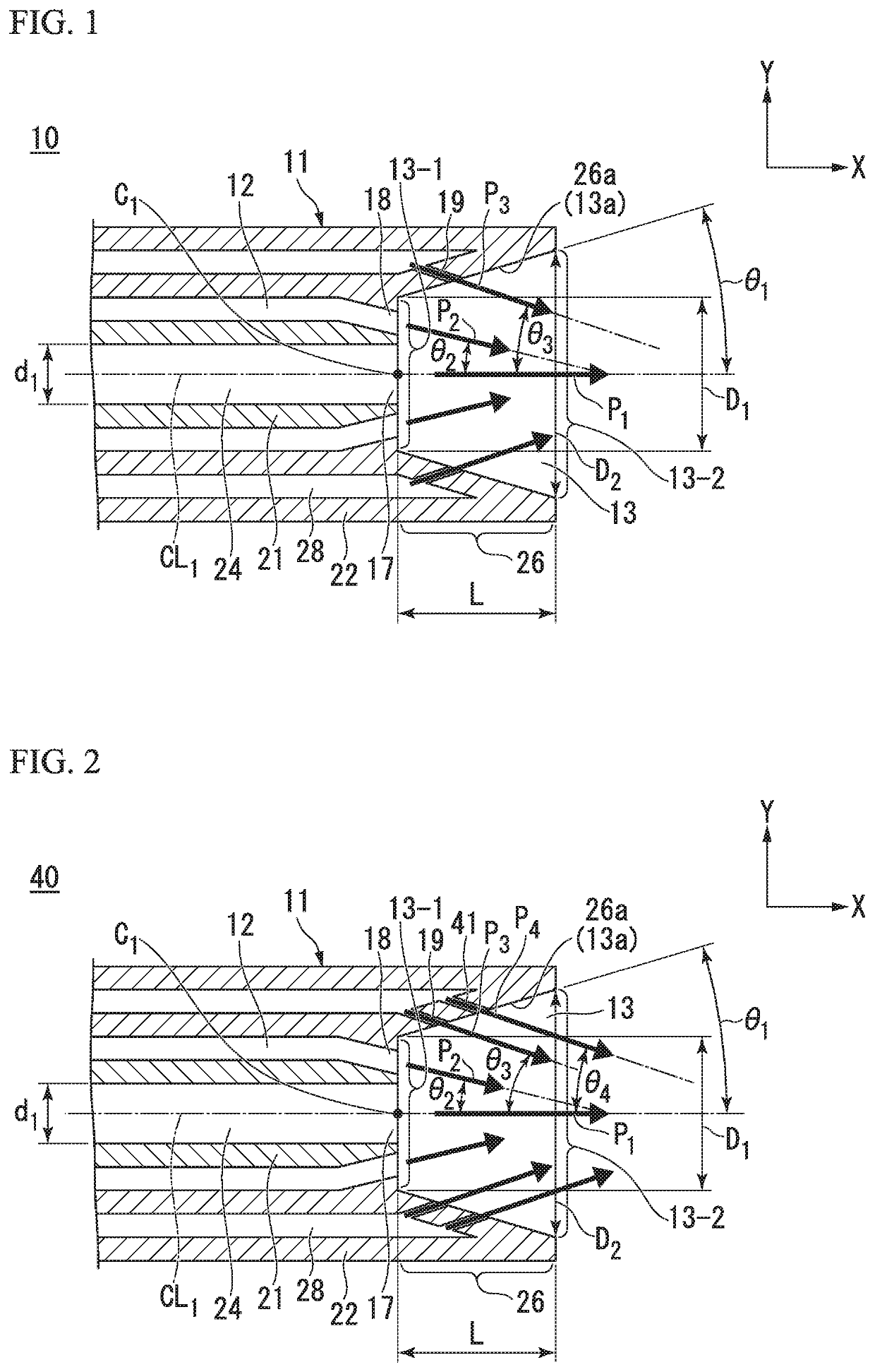
[0040]FIG. 1 is a cross-sectional view that schematically shows the outline configuration of the main portions of the gas fuel burner according to the first embodiment of the present invention. In FIG. 1, the X direction denotes the direction (in other words, a predetermined direction) that the burner body 11 extends, and the Y direction denotes a direction that is orthogonal to the X direction.

[0041]Also, in FIG. 1, P1 denotes the direction in which a first oxidation agent is discharged (hereinbelow called the “first oxidation agent discharge direction P1”), P2 denotes the direction in which a gas fuel is discharged (hereinbelow called the “gas fuel discharge direction P2”), and P3 denotes the direction in which a second oxidation agent is discharged (hereinbelow called the “second oxidation agent discharge direction P3”).

[0042]Referring to FIG. 1, a gas fuel burner 10 of the first embodiment comprises a burner body 11, a gas fuel supply path 12, a combustion chamber 13, a first ox...

second embodiment

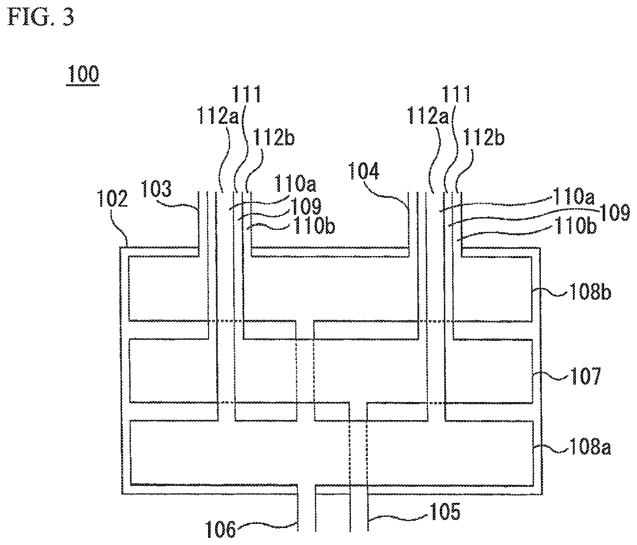
[0105]FIG. 2 is a cross-sectional view that schematically shows the outline configuration of the main portions of the gas fuel burner according to the second embodiment of the present invention. In FIG. 2, P4 denotes the direction in which a third oxidation agent is discharged (hereinbelow referred to as the “third oxidation agent discharge direction P4”).

[0106]In FIG. 2, constituent portions that are the same as those of the gas fuel burner 10 of the first embodiment shown in FIG. 1 are denoted by the same reference numerals.

[0107]The gas fuel burner 40 of the second embodiment shown in FIG. 2 is constituted similarly to the gas fuel burner 10 of the first embodiment, except for a third oxidation agent discharge port 41 being additionally provided in the constitution of the gas fuel burner 10 of the first embodiment.

[0108]The third oxidation agent discharge port 41 in the gas fuel burner 40 of the second embodiment is disposed more toward the second circular face 13-2 side of the s...


PUM


Abstract

The gas fuel burner of the present invention has: a first oxidation agent discharge port that is disposed in the center of a first circular face constituting a combustion chamber having a truncated cone shape that expands from the basal end toward the distal end of a burner body and that discharges a first oxidation agent in the direction that the center axis of the burner body extends; a gas fuel discharge port that is disposed on the outside of the first oxidation agent discharge port and that discharges gas fuel in a direction intersecting the direction that the center axis extends; and a second oxidation agent discharge port that is disposed on a side face of the combustion chamber and that discharges a second oxidation agent in a direction intersecting the direction that the center axis extends.

Description

[0001]This application is the U.S. national phase of International Application No. PCT / JP2015 / 085032 filed 15 Dec. 2015, which designated the U.S. and claims priority to JP Patent Application No. 2015-037973 filed 27 Feb. 2015, the entire contents of each of which are hereby incorporated by reference.BACKGROUND OF THE INVENTIONField of the Invention[0002]The present invention relates to a gas fuel burner suitable for heating an object to be heated by convection heat transfer, and a method for heating with a gas fuel burner.[0003]When heating by convection heat transfer by causing a flame formed by a gas fuel burner to directly impinge upon an object to be heated, it is required for the flame temperature to be high and the axial speed of the flame to be fast.[0004]In the case of the object to be heated being a material that oxidizes, if there is a large amount of unreacted oxygen present when the flame impinges on the object to be heated, the problem arises of oxidation of the object...

Claims


Application Information

Patent Timeline
Patent Type & Authority Patents(United States)
IPC IPC(8): F23D14/22F23D14/60F23D14/58
CPCF23D14/60F23D14/22F23D14/58F23D14/32
Inventor YAMAMOTO, YASUYUKIIINO, KIMIO
Owner NIPPON SANSO CORP
Why Eureka
Try Eureka