Power storage unit and power storage system

Active Publication Date: 2020-06-09
SANYO ELECTRIC CO LTD
View PDF8 Cites 3 Cited by
  • Summary
  • Abstract
  • Description
  • Claims
  • Application Information

AI Technical Summary

Benefits of technology

[0011]According to the present invention, the voltage or the remaining capacity in power s

Problems solved by technology

However, when both-end voltage of the assembled battery is high, power consumed in the resistor becomes high.
Thus, heat generation in t

Method used


Image

  • Power storage unit and power storage system
  • Power storage unit and power storage system
  • Power storage unit and power storage system

Examples


Embodiment Construction

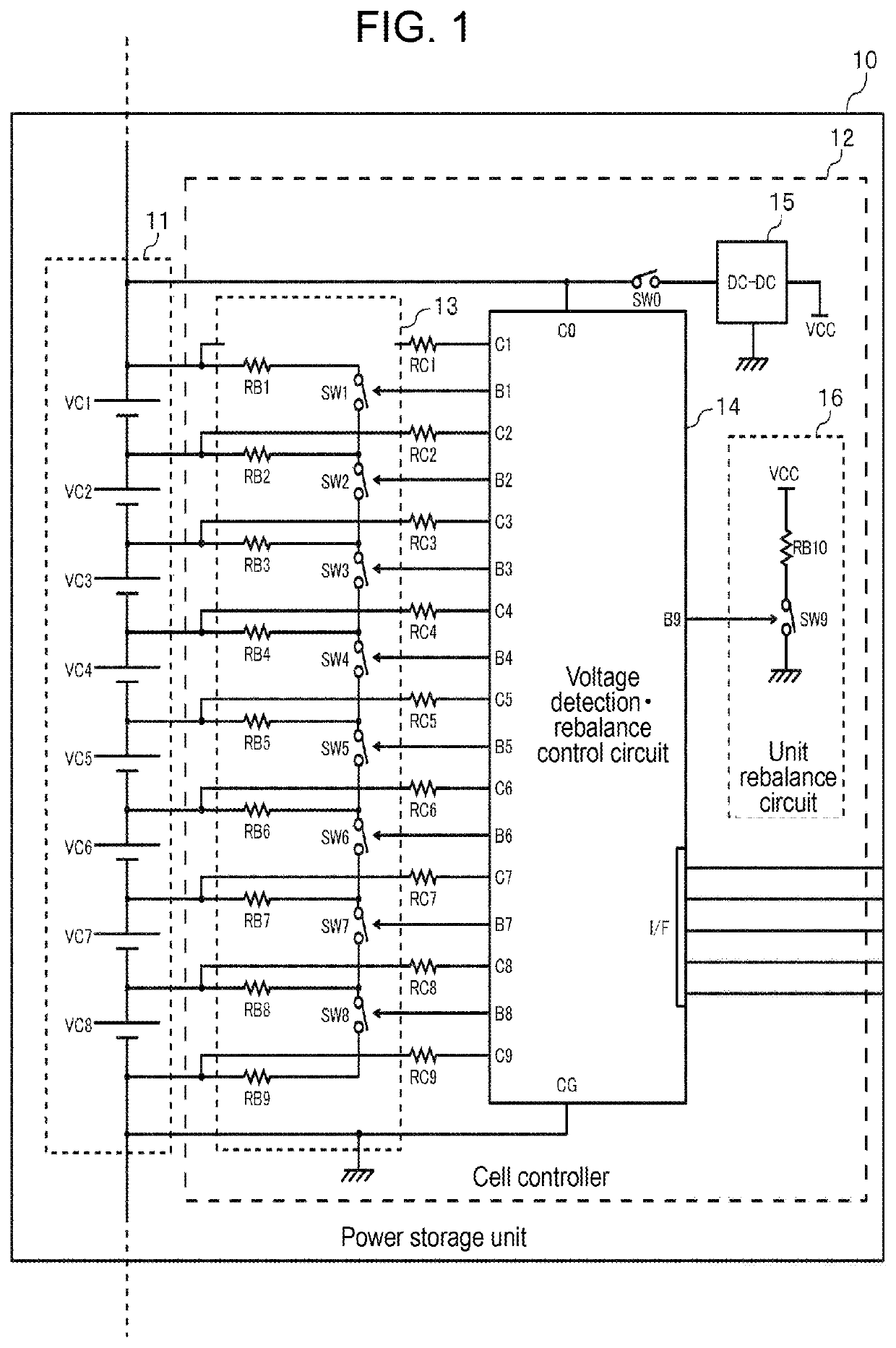
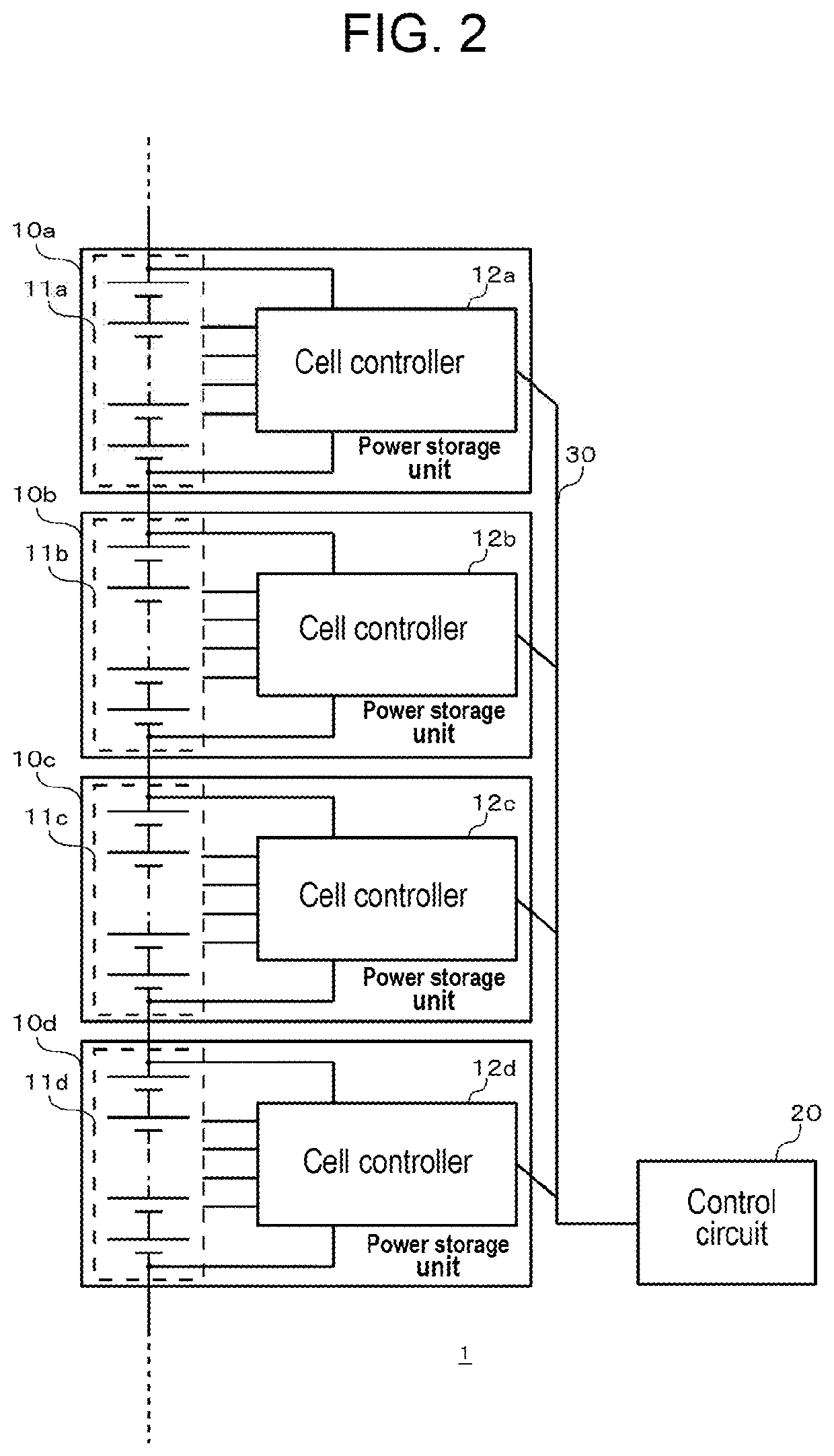
[0015]FIG. 1 is a view of a configuration of power storage unit 10 according to an exemplary embodiment of the present invention. FIG. 2 is a view of a configuration of power storage system 1 where a plurality of power storage units 10 of FIG. 1 are connected in series. As shown in FIG. 1, power storage unit 10 is provided with assembled battery 11 and cell controller 12. Assembled battery 11 is configured of a plurality of single cells VC1 to VC8 connected in series. The single cell is configured of one piece of a single battery, or a plurality of single batteries connected in series. An example of the single cell includes any one of lithium ion battery cell, nickel hydride battery cell, and electric double-layer capacitor cell. Herein, the single cell is assumed to be the lithium ion battery cell, for example. The nominal voltage of the lithium ion battery cell is 3.6 to 3.7 V. As eight pieces of single cells VC1 to VC8 are connected in series in the example of FIG. 1, the both-en...


PUM


Abstract

A voltage detection circuit detects the voltage of a plurality of serially connected cells in a power storage unit. The voltage detection circuit receives a supply of a power supply voltage from both ends of the plurality of cells. A DC-DC converter converts the voltage between both ends of the plurality of cells into another DC voltage. An adjustment circuit adjusts the power consumption of the plurality of cells. The adjustment circuit operates using the DC voltage generated by the DC-DC converter as the power supply voltage.

Description

TECHNICAL FIELD[0001]The present invention relates to a power storage unit for managing a plurality of cells connected in series, and a power storage system having a plurality of power storage unites.BACKGROUND ART[0002]In recent years, hybrid vehicles (HV), plug-in hybrid vehicles (PHV), and electric vehicles (EV) are being spread. Secondary batteries as a key device are installed in these vehicles. As secondary batteries for the vehicle, the nickel hydride batteries and the lithium ion batteries are spread. In the future, it is expected that spread of the lithium ion batteries having high energy density are accelerated.[0003]Since the operable voltage range and the prohibited voltage range in the lithium ion batteries are close, the stricter voltage management is necessary in the lithium ion batteries than other types of batteries. When an assembled battery in which a plurality of the lithium ion battery cells are connected in series is used, a voltage detection circuit is provide...

Claims


Application Information

Patent Timeline
IPC IPC(8): H02J7/00H01M10/48H01M10/44H02J1/10H01M50/569
CPCH02J7/0024H02J7/0018H01M10/482H02J7/0016H01M10/441H02J7/0047H02J1/102H02J2207/20Y02E60/10H02J7/0048H01M50/569
Inventor YANO, JUNYAMATSUBARA, TOMOYUKIMUKAE, HIDETSUGUASAKURA, JUN
Owner SANYO ELECTRIC CO LTD
Why Eureka
Try Eureka