
Surface plasmon-enhanced fluorescence measurement device and surface plasmon-enhanced fluorescence measurement method

a fluorescence measurement and fluorescence technology, applied in the direction of fluorescence/phosphorescence, optical radiation measurement, instruments, etc., can solve the problem of downsizing the measurement apparatus and achieve the effect of high sensitiveness

Active Publication Date: 2020-06-23
OTSUKA PHARM CO LTD
View PDF8 Cites 0 Cited by
  • Summary
  • Abstract
  • Description
  • Claims
  • Application Information

AI Technical Summary

Benefits of technology

The invention improves a device and method for measuring substances using gas chromatography and single photon detection. The new technology makes it possible to detect small amounts of substances with higher sensitivity.

Problems solved by technology

PC-SPFS, which is a mainstream method today, has a challenge of downsizing a measurement apparatus since a prism is used and an incident angle of excitation light on a metal film is large.

Method used


Image

  • Surface plasmon-enhanced fluorescence measurement device and surface plasmon-enhanced fluorescence measurement method
  • Surface plasmon-enhanced fluorescence measurement device and surface plasmon-enhanced fluorescence measurement method
  • Surface plasmon-enhanced fluorescence measurement device and surface plasmon-enhanced fluorescence measurement method

Examples


embodiment 1

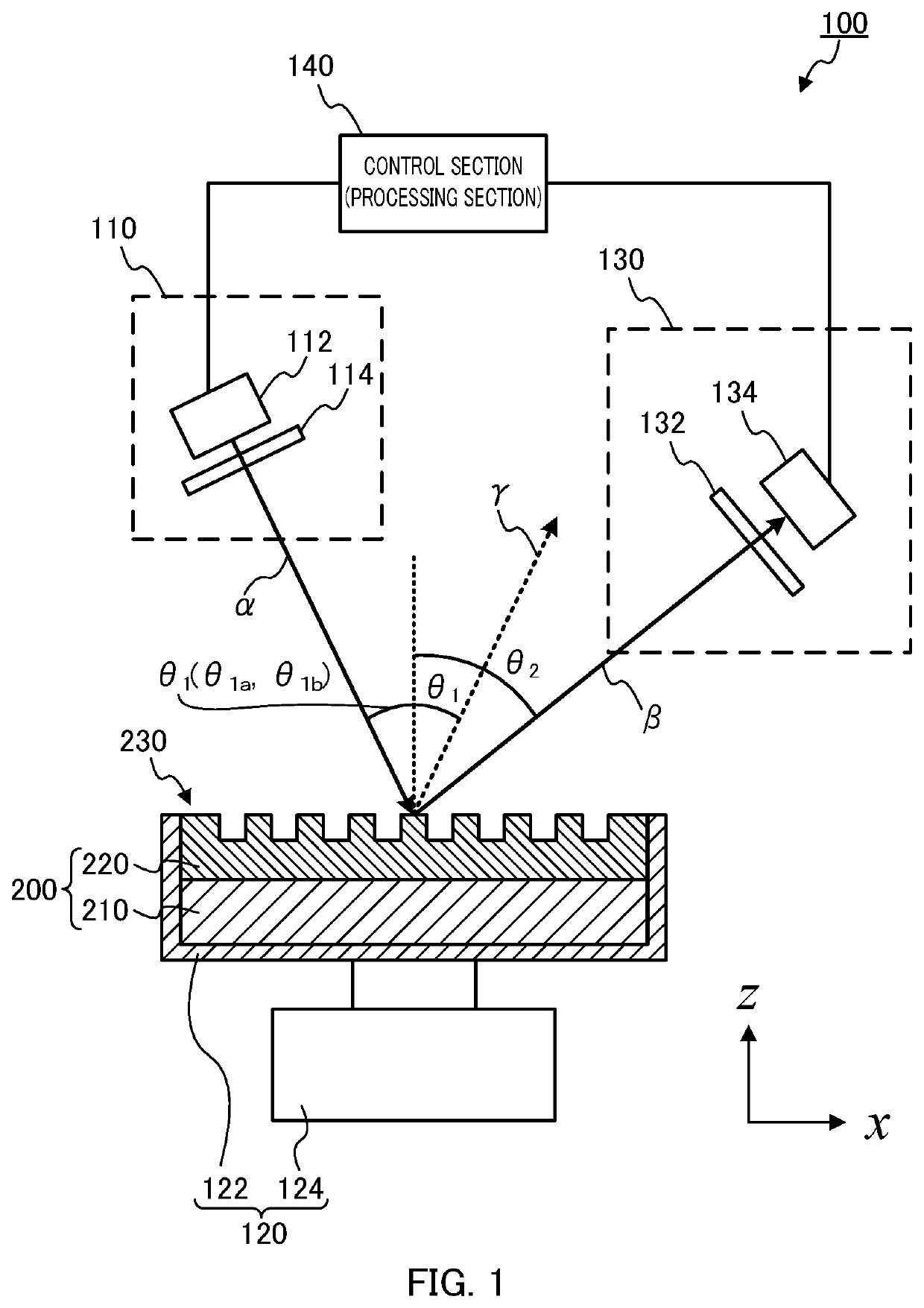
[0029]FIG. 1 is a schematic view illustrating a configuration of a surface plasmon-field enhanced fluorescence measurement apparatus (SPFS apparatus) 100 according to Embodiment 1 of the present invention.

[0030]As illustrated in FIG. 1, SPFS apparatus 100 includes excitation light irradiation unit 110, rotation section 120, fluorescence detection unit 130, and control section 140. SPFS apparatus 100 is used while chip 200 is mounted on chip holder 122 in rotation section 120. Detection chip 200 will be described first, followed by the description of SPFS apparatus 100.

[0031](Configurations of Chip and SPFS Apparatus)

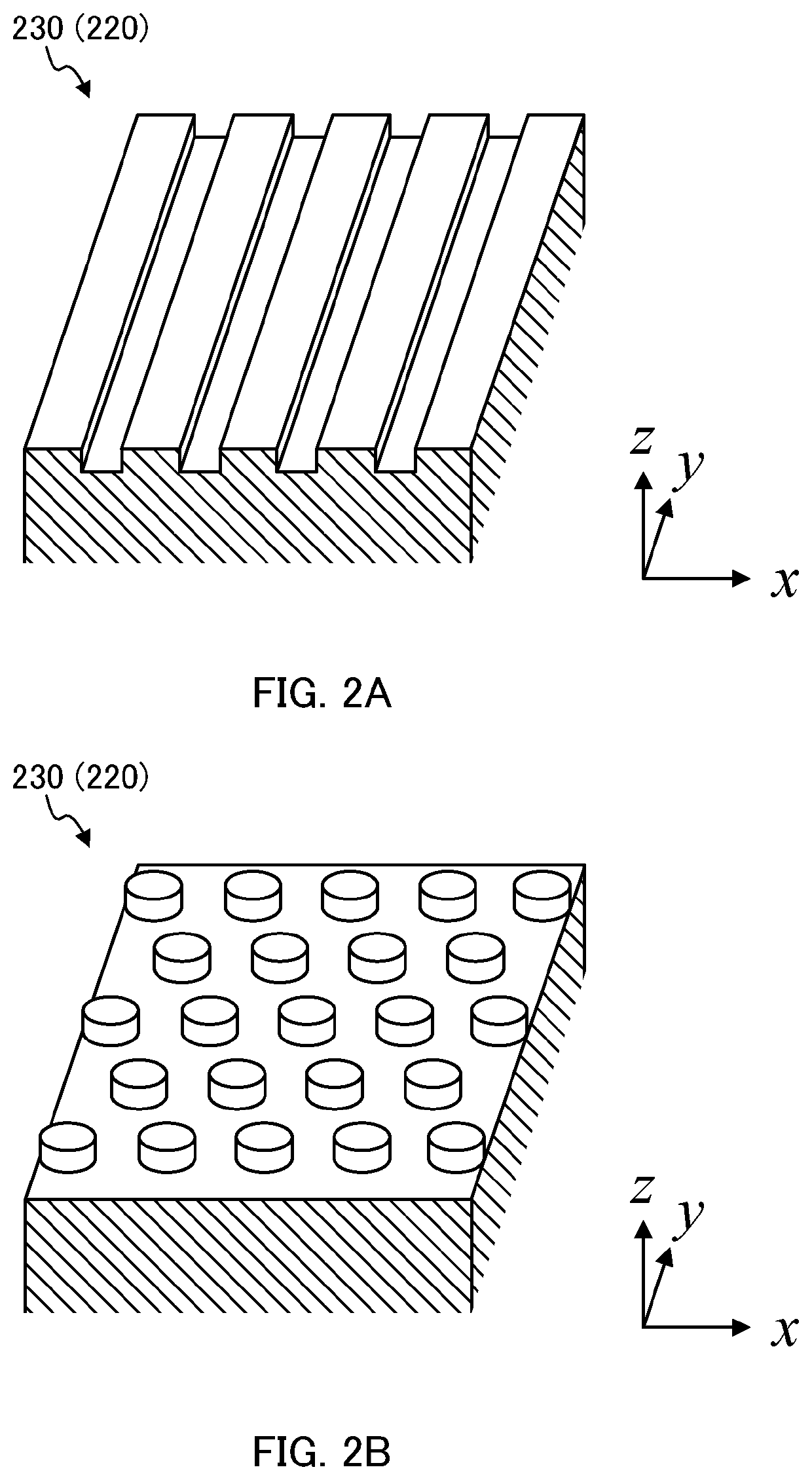
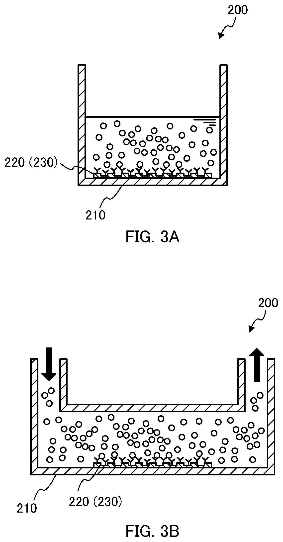
[0032]Chip 200 includes substrate 210 and metal film 220 formed on substrate 210. Diffraction grating 230 is formed in metal film 220. A ligand (e.g., primary antibody) is immobilized above diffraction grating 230, and a surface of diffraction grating 230 functions as a reaction site for binding a ligand and an analyte. In FIG. 1, a ligand and an analyte are not shown.

[0...

embodiment 2

[0099]SPFS apparatus 300 according to Embodiment 2 is different from SPFS apparatus 100 according to Embodiment 1 in that the configuration of rotation section 320 differs from that of rotation section 120. Thus, the configuration of rotation section 320 will be primarily described. The same components as those of SPFS apparatus 100 are denoted by the same numerals, and thus their descriptions will be omitted. Chip 200 is the same as chip 200 according to Embodiment 1, and thus the description will be omitted.

[0100](Configuration of SPFS Apparatus)

[0101]FIG. 8 is a schematic view illustrating a configuration of SPFS apparatus 300 according to Embodiment 2. As illustrated in FIG. 8, SPFS apparatus 300 according to Embodiment 2 includes excitation light irradiation unit 110, rotation section 320, fluorescence detection unit 130, and control section 140.

[0102]Rotation section 320 changes the polarization direction of excitation light α relative to diffraction grating 230. Rotation sect...


PUM

PropertyMeasurementUnit
thicknessaaaaaaaaaa
thicknessaaaaaaaaaa
sizeaaaaaaaaaa

Abstract

The surface plasmon-enhanced fluorescence measurement device has: a light source that irradiates the diffraction grating with a linearly polarized excitation light; a rotating part that changes the direction of the optical axis of the excitation light with respect to the diffraction grating when seen in plan view, or changes the polarization direction of the excitation light with respect to the diffraction grating; a polarizer that extracts linearly polarized light from the fluorescence emitted from the fluorescent substance; and a light detection unit that detects the linearly polarized light extracted by the polarizer.

Description

TECHNICAL FIELD[0001]The present invention relates to a surface plasmon-field enhanced fluorescence measurement apparatus and a surface plasmon-field enhanced fluorescence measurement method for detecting, utilizing surface plasmon resonance, the presence or an amount of an analyte contained in a sample.BACKGROUND ART[0002]In a clinical test or the like, highly sensitive and quantitative detection of a trace amount of analyte, such as a protein or DNA, would allow a quick understanding of a patient's condition and the subsequent his / her treatment. For this reason, there is a need for a method of detecting a trace amount of analyte highly sensitively and quantitatively.[0003]As a highly sensitive method of detecting an analyte, surface plasmon-field enhanced fluorescence spectroscopy (hereinafter abbreviated as “SPFS”) is known. SPFS utilizes surface plasmon resonance (hereinafter abbreviated as “SPR”) generated upon irradiation of a metal film with light under predetermined conditio...

Claims


Application Information

Patent Timeline
Patent Type & Authority Patents(United States)
IPC IPC(8): G01N33/553G01N21/64G01N33/543G01J3/18G01J3/02
CPCG01N21/6445G01J3/0202G01J3/18G01N21/648G01N33/54373G01N33/553G01N21/6428G01J3/0237G01J3/0224G01N2021/6463G01N2021/6439G01N2201/0683
Inventor NAKAMURA, YUKITONAGAE, KOSUKEKAYA, TAKATOSHI
Owner OTSUKA PHARM CO LTD
Learn More