Transformer
a transformer and transformer technology, applied in the field of transformers, can solve problems such as weight, and achieve the effects of reducing the weight of the transformer, reducing the size of the transformer, and reducing the cos
- Summary
- Abstract
- Description
- Claims
- Application Information
AI Technical Summary
Benefits of technology
Problems solved by technology
Method used
Image
Examples
first embodiment
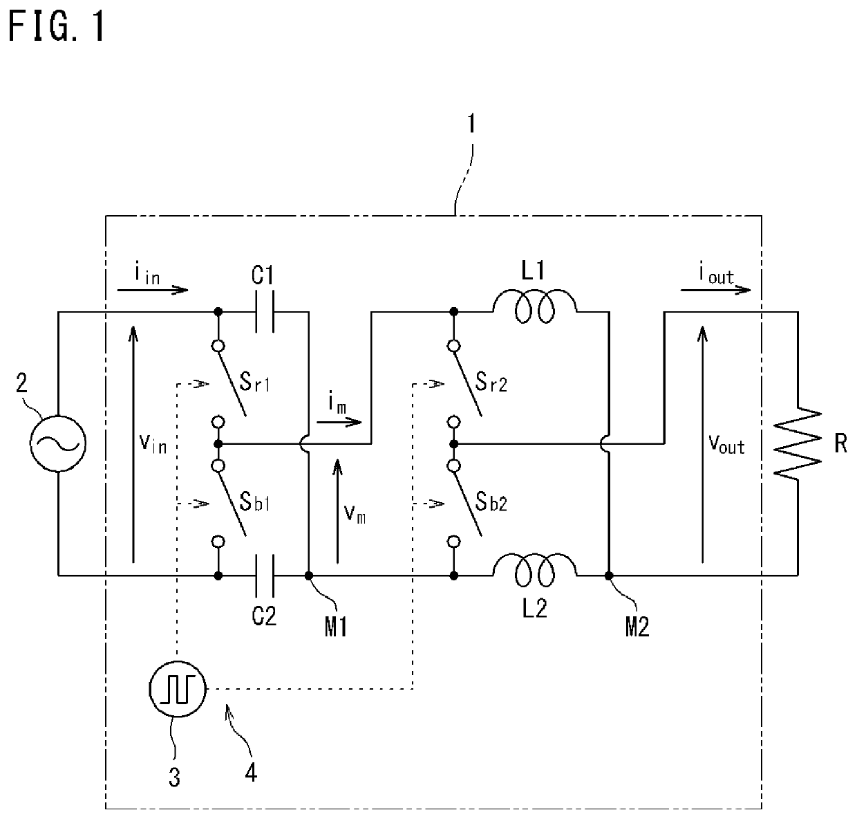
[0145]FIG. 1 is a circuit diagram showing a transformer 1 according to the first embodiment. In FIG. 1, the transformer 1 is provided between an AC power supply 2 and a load R (R also denotes a resistance value). The transformer 1 includes a pair of capacitors C1 and C2, a pair of inductors L1 and L2, four switches Sr1, Sr2, Sb1, and Sb2, and a switching control section 3 which performs ON / OFF control of the switches Sr1, Sr2, Sb1, and Sb2. A switching frequency of the switching control section 3 is, for example, about 1 MHz.
[0146]The pair of capacitors C1 and C2 may have the same capacitance value, or may have different capacitance values. The same applies to the inductance values of the pair of inductors L1 and L2.
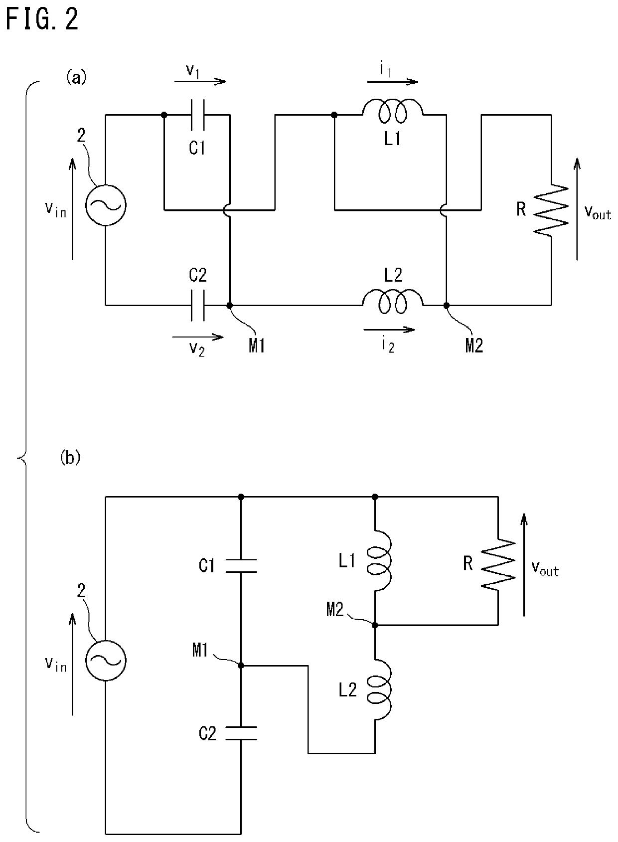
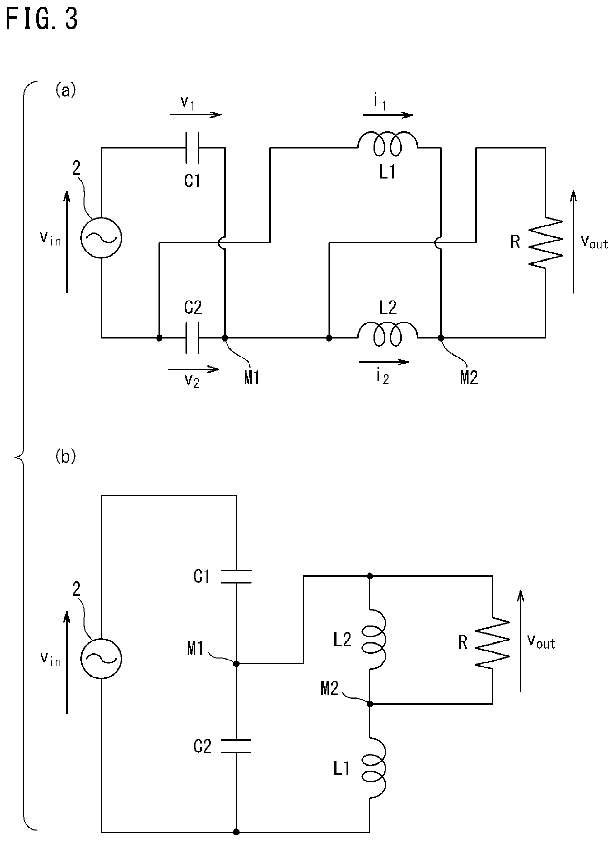
[0147]The switches Sr1, Sr2, Sb1, and Sb2 and the switching control section 3 form a switch device 4 which switches the state of circuit connection of the transformer 1. The switches Sr1 and Sr2 operate in synchronization with each other, and the switches Sb1 and Sb2 ope...
second embodiment
[0193]FIG. 7 is a circuit diagram showing a transformer 1 according to the second embodiment. This transformer 1 is substantially the same as in FIG. 1, but is different from FIG. 1 in that the AC power supply 2 and the load R are replaced with each other. In this case, input and output are reversed, and input voltage is stepped up to be quadrupled. Along with the stepping-up, output current becomes ¼. The circuit parameter condition is the same as in the first embodiment.
[0194]FIG. 8 is a waveform diagram in which an upper graph shows input voltage to the transformer 1 and a lower graph shows input current to the transformer 1. FIG. 9 is a waveform diagram in which an upper graph shows output voltage from the transformer 1 and a lower graph shows output current from the transformer 1. As is obvious from comparison between FIG. 8 and FIG. 9, voltage is transformed to be quadrupled, and along with this, current becomes ¼.
[0195]Thus, the transformer 1 shown in FIG. 1 or FIG. 7 is reve...
third embodiment
[0196]FIG. 10 is a circuit diagram showing a transformer 1 according to the third embodiment. This transformer 1 is different from FIG. 1 in placement of the switches Sr1, Sr2, Sb1, and Sb2, but the other configuration is the same as in FIG. 1. That is, in FIG. 10, the switches Sb2 and Sr2 on the side of the inductors L1 and L2 are upside down as compared to FIG. 1. As for operation timing, as in the case of FIG. 1, the switches Sr1 and Sr2 operate in synchronization with each other, and the switches Sb1 and Sb2 operate in synchronization with each other. A pair of the switches Sr1 and Sr2 and a pair of the switches Sb1 and Sb2 operate so as to be alternately turned on exclusively from each other. The circuit parameter condition is the same as in the first embodiment.
[0197]In the circuit in FIG. 10, the switches Sb2 and Sr2 on the inductor side perform switching operations in reverse phase as compared to the circuit in FIG. 1.
[0198]Such switch placement and operation can reverse the...
PUM
 Abstract
Description
Claims
Application Information
 - R&D
- Intellectual Property
- Life Sciences
- Materials
- Tech Scout
- Unparalleled Data Quality
- Higher Quality Content
- 60% Fewer Hallucinations
Browse by: Latest US Patents, China's latest patents, Technical Efficacy Thesaurus, Application Domain, Technology Topic, Popular Technical Reports.
© 2025 PatSnap. All rights reserved.Legal|Privacy policy|Modern Slavery Act Transparency Statement|Sitemap|About US| Contact US: help@patsnap.com


