High energy density multilayer battery cell with thermally processed components and method for making same

a multi-layer battery cell, high energy density technology, applied in the direction of electrode manufacturing process, electrochemical generator, vapour deposition manufacturing, etc., can solve the problems of difficult to calculate the optimal materials and layer thicknesses of the substrate, difficult to calculate the process rate required to produce battery cells profitably, and limited design of solid-state battery cells that can be produced at scale. , to achieve the effect of improving the connection of two electrode layers, high energy/capacity, and easy device splitting

Active Publication Date: 2020-07-07
DYSON TECH LTD
View PDF8 Cites 6 Cited by
  • Summary
  • Abstract
  • Description
  • Claims
  • Application Information

AI Technical Summary

Benefits of technology

[0008]The results of the invention are a solid-state battery that has energy density above 300 Wh / L. Although this has been achieved using some battery systems that are designed with liquid or gel electrolytes, no solid-state batteries with ceramic electrolytes have come close to achieving this level of energy density. Furthermore, the ceramic electrolytes and the design that is employed eliminates the occurrence of lithium dendrites and other undesirable side reactions that occurs between the liquid or gel electrolyte and the battery materials in conventional wound lithium-ion batteries. Additionally, the solid ceramic electrolyte that is utilized in this invention also eliminates the occurrence of internal short circuits that are a major failure mechanism in lithium-ion battery cells that utilize a polymer separator. In an embodiment, a method of producing a monolithically integrated high energy density solid-state battery device includes forming one or more stacked monolithically integrated high energy density solid-state electrochemical cells sequentially or individually on a substrate, each of the high energy density solid-state electrochemical cells comprising: a first barrier layer, a cathode current collector formed over the first barrier layer, a cathode layer comprising an amorphous or crystalline charge carrier intercalated metal-1, metal-2, and metal-3 oxide or phosphate compound formed over the cathode current collector, a solid state anode layer configured for electrochemical insertion or ions plating during a charge process and a discharge process, an anode current collector formed over the solid state anode layer, and a second barrier layer configured to prevent oxidation of the negative electrode material; annealing the one or more stacked monolithically integrated high energy density solid-state electrochemical cells to a target temperature of greater than 600° C. for at least 60 minutes; and connecting the one or more stacked monolithically integrated high energy density solid-state electrochemical cells electrically in series or in parallel, wherein the one or more stacked monolithically integrated high energy density solid-state electrochemical cells are terminated using one of laser ablation, selective etching, or mechanical masking to form a monolithically integrated high energy density solid-state battery device.
[0016]In an embodiment, the present invention provides a method of manufacturing a monolithically integrated high energy density solid-state battery device includes extra steps, other than necessary steps of depositing electrode materials, which include steps to crystallize the active material layer such as cathode and anode in-situ or post-deposition, to deposit detaching / smoothing / bounding layer between two electrode material layers, or to carbonize detaching / smoothing / bounding layer between two electrode material layers. Some of the solid-state battery device requires the cathode / anode layer to have crystalline structure to achieve high energy / capacity. Therefore, it is necessary to crystallize the cathode / anode electrode. There are two approaches inducing crystalline to cathode / anode electrode layer. A first approach induces crystalline to the cathode / anode electrode film by providing heat as the deposition of the same electrode layer progress. A second approach induces crystalline to the cathode or anode electrode by providing heat to whole device after deposition process. Further, the connection of electrochemical component layers determines the charge and discharge capability, and cycle life. In some cases, it is necessary to provide bounding or smoothing layer before depositing the next electrode material layer so that the material properties of such layer can improve the connection of two electrode layers. For some case, it is necessary to provide layer material between electrode materials served as detaching layer so that it is easier to split the device into two or more for packaging purpose.
[0019]In an embodiment, the present invention provides a list of material for detaching / smoothing / bounding layer, which can be Li, polymer or combinations thereof. The Li material can be used as bounding layer, because of its mechanical properties such as low modulus so that it could mitigate the residual stresses induced due to mismatch thermal expansion of new layer and existing layers during the deposition process, and high electrical conductivity so that it could reduce the electrical loss between the two electrode layers, especially between electrolyte and anode. On the other hand, polymer material can be used as detaching / smoothing / bounding layer, because of its material composition and its deposition process. Most of the polymer is a compound of carbon and hydrogen. Therefore, polymer film after burning would result in carbonized film. This carbonized polymer film could serve as detaching layer because it most likely is in pieces; therefore, the whole solid-state battery device can be separated into two parts from this carbonized polymer film. The deposition method for polymer layer comprises,

Problems solved by technology

The design of a solid state battery cell that can be produced at scale has been limited by the absence of computational design tools and the high capital expenditures required to arrive near an optimized design through a trial-and-error process.
Without these tools it would be difficult to calculate the optimal materials and layer thicknesses for the substrate, the cathode current collector, the cathode, the solid state electrolyte, the anode, and the anode current collector.
It would also have been difficult to calculate the process rates required to produce battery cells profitably.
Although this has been achieved using some battery systems that are designed with liquid or gel electrolytes, no solid-state batteries with ceramic electrolytes have come close to achieving this level of energy density.

Method used


Image

  • High energy density multilayer battery cell with thermally processed components and method for making same
  • High energy density multilayer battery cell with thermally processed components and method for making same
  • High energy density multilayer battery cell with thermally processed components and method for making same

Examples


example 1

ion of Battery Terminations in Edge of the High Energy Density Solid State Battery

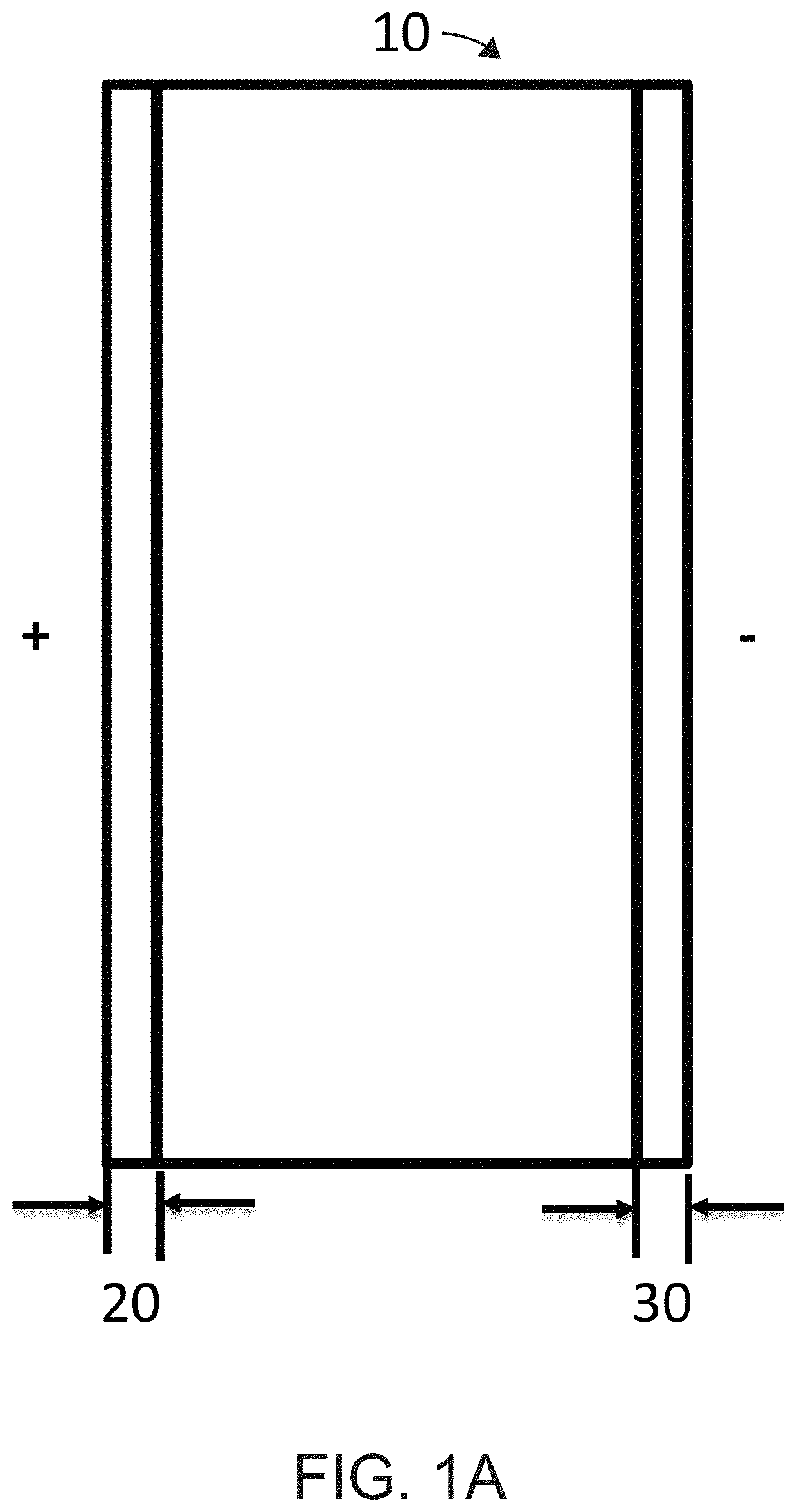
[0054]FIG. 1A is a simplified top view of a multi-layered solid state cell according to an embodiment of the present invention. FIG. 1A illustrates the definition of the t1, which is the distance from the side of the battery to the ablated edge of the electrode, such as 20 and 30. The 10 is the top view of the multi-stack of solid state thin film cell.

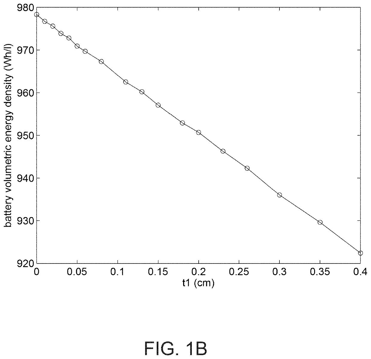
[0055]FIG. 1B is a graph of the relationship between battery volumetric energy density and a thickness t1 (cm) of a multi-layered solid state cell according to an embodiment of the present invention. FIG. 1B demonstrates the effect of the length edge of high energy density, which is denoted as t1 in this example. As the length, t1, increased from 0 to 0.4 cm, the energy density of the battery decreased from about 980 Wh / L to about 920 Wh / L. It clearly illustrated the importance the controlling t1 in order to achieve high energy density of battery. This ex...


PUM

PropertyMeasurementUnit
temperatureaaaaaaaaaa
energy densityaaaaaaaaaa
temperatureaaaaaaaaaa

Abstract

A method of producing a monolithically integrated high energy density solid-state battery device. The method can include positioning a substrate and depositing one or more stacked monolithically integrated high energy density solid-state electrochemical cells in series or in parallel configurations sequentially or individually. Each of these cells can have a first barrier layer, a cathode current collector deposited overlying the first barrier layer, a cathode overlying the electrically conductive layer, an anode, an anode current collector deposited overlying the solid state layer of negative electrode material, and a second barrier layer. The method can also include rapidly heating the one or more stacked cells to a target temperature for at least 60 minutes, and connecting and terminating the one or more stacked monolithically integrated high energy density solid-state electrochemical cells electrically in series or in parallel, to from a monolithically integrated high energy density solid-state battery device.

Description

FIELD OF THE INVENTION[0001]The present invention relates to techniques for manufacturing solid state electrochemical devices. More particularly, the present invention provides high energy density multilayer battery cell with thermally processed components.BACKGROUND OF THE INVENTION[0002]Batteries can be used for a variety of applications such as portable electronics (cell phones, personal digital assistants, music players, video cameras, and the like), power tools, power supplies for military use (communications, lighting, imaging and the like), power supplies for aerospace applications (power for satellites), and power supplies for vehicle applications (hybrid electric vehicles, plug-in hybrid electric vehicles, and fully electric vehicles). The design of such batteries is also applicable to cases in which the battery is not the only power supply in the system, and additional power is provided by a fuel cell, other battery, IC engine or other combustion device, capacitor, solar c...

Claims


Application Information

Patent Timeline
Patent Type & Authority Patents(United States)
IPC IPC(8): H01M10/04H01M10/0585H01M10/0562H01M4/1391H01M4/04H01M6/40
CPCH01M4/0428H01M10/0562H01M4/1391H01M4/0421H01M6/40H01M10/04H01M10/0585H01M4/04Y02E60/10Y02P70/50
Inventor SASTRY, ANN MARIEWANG, CHIA-WEICHEN, YEN-HUNGZHANG, XIANGCHUNKIM, HYONCHEOLCHUNG, MYOUNGDO
Owner DYSON TECH LTD
Why Eureka
Try Eureka