
System and process for converting waste plastic into fuel

a waste plastic and waste technology, applied in the direction of charging devices, combustible gas purification/modification, energy input, etc., can solve the problems of inability to continuously fill and discharge, fire hazards, sealing mechanisms,

Active Publication Date: 2020-08-04
BRAVEN ENVIRONMENTAL LLC
View PDF154 Cites 8 Cited by
  • Summary
  • Abstract
  • Description
  • Claims
  • Application Information

AI Technical Summary

Problems solved by technology

A challenge with using large vessels is their inability to fill and discharge continuously as these systems use a batch fill to insert plastic and then heat the product with sealed ends.
A second problem with large vessels of conventional system includes drawbacks with the sealing mechanisms.
Due to this expansion, oxygen can leak into the vessels creating a fire hazard.
A third challenge with the current known art is that the start of time of the pyrolysis reaction is prolonged due to the fact that the vessel needs to be started up when it is cold and the oxygen needs to be evacuated before heating.
This is an extremely time intensive process.
Another problem with prior art systems includes vessels that require a cool down period before cleaning, for example, in order to access the interior structures.
The char removal process involved with the prior art is cumbersome and extremely dirty because of the nature of cleaning as the vessel collects char on the wall.
This is very time consuming and expensive due to the low efficiency of combination of heating, cooling, and cleaning.
This is expensive and can be hazardous.
The inability to switch from a certain homogenous stream to a mixed plastic stream requires re-configuration of the equipment.
Plastic bags, film, and light density plastics present a problem to standard shredders and feeding mechanisms due to the wrapping effect and bridging that occurs.
Although knife cutting devices will work to resolve this problem, they will not allow for hard contaminates to pass through the cutting blades.
The hard contaminates will damage the cutting edge and even stop the cutter rotation.

Method used


Image

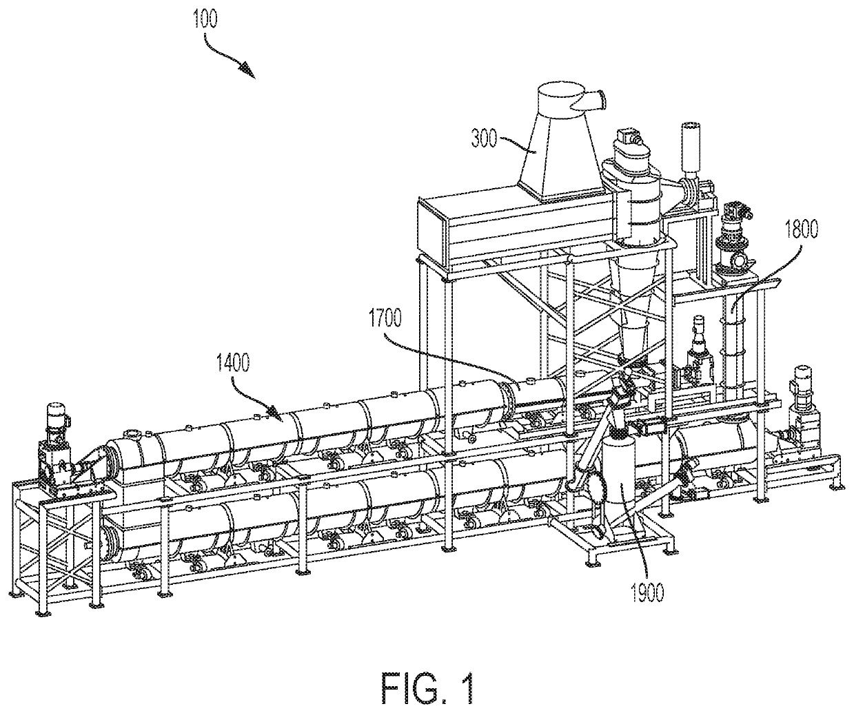
  • System and process for converting waste plastic into fuel
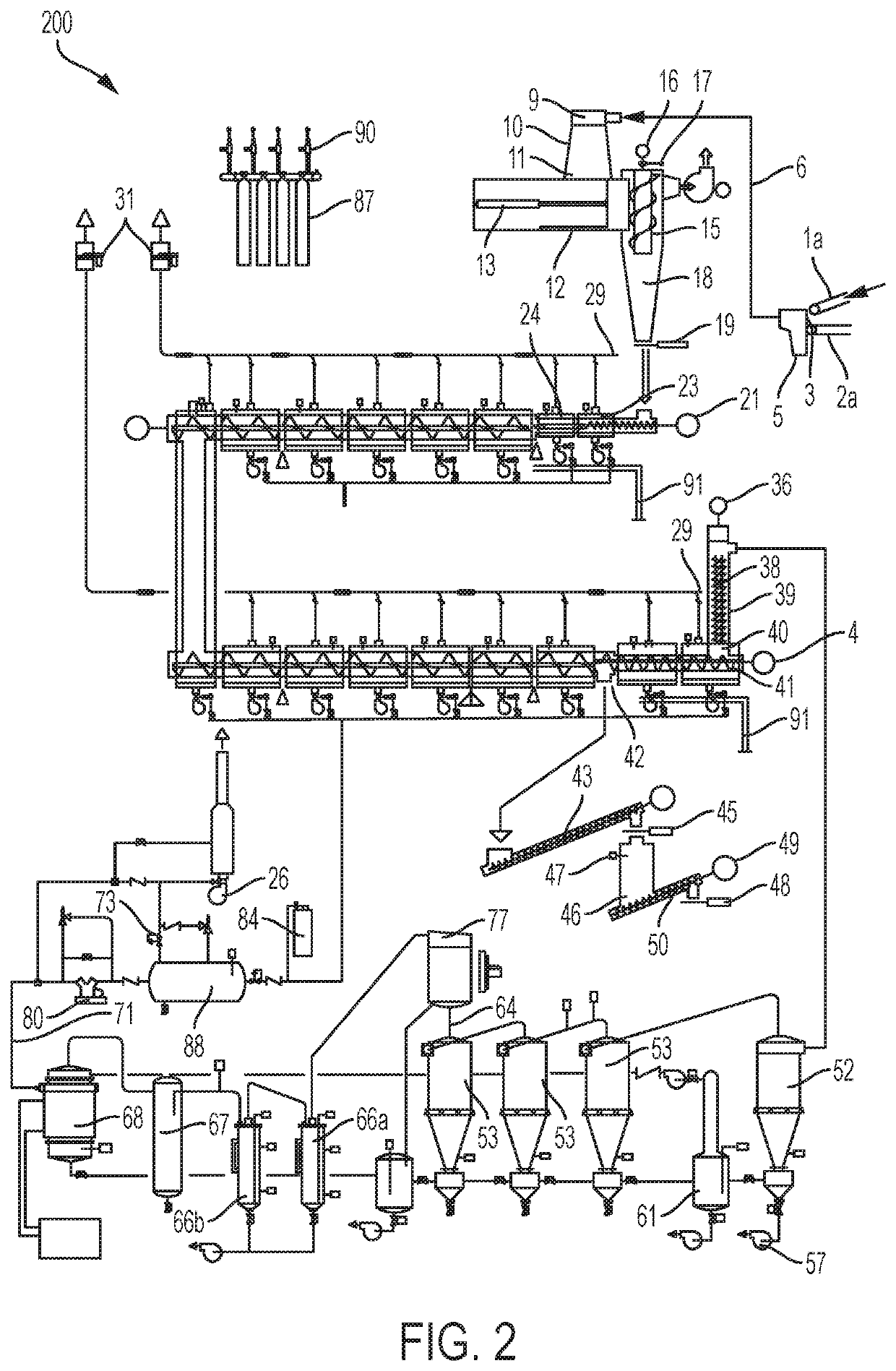
  • System and process for converting waste plastic into fuel
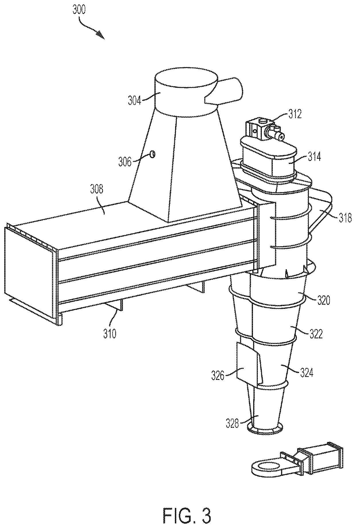
  • System and process for converting waste plastic into fuel

Examples


Embodiment Construction

Definitions

[0033]Where the definition of terms departs from the commonly used meaning of the term, applicant intends to utilize the definitions provided below, unless specifically indicated.

[0034]It is to be understood that the foregoing general description and the following detailed description are exemplary and explanatory only and are not restrictive of any subject matter claimed. In this application, the use of the singular includes the plural unless specifically stated otherwise. It must be noted that, as used in the specification and the appended claims, the singular forms “a,”“an” and “the” include plural referents unless the context clearly dictates otherwise. In this application, the use of “or” means “and / or” unless stated otherwise. Furthermore, use of the term “including” as well as other forms, such as “include”, “includes,” and “included,” is not limiting.

[0035]For purposes of the present invention, the term “comprising”, the term “having”, the term “including,” and va...


PUM


Abstract

An apparatus is provided for processing reusable fuel comprising: a continuous material supply assembly; a heated airlock feeder configured to continuously receive and process the material supply received therein; a reactor configured to receive the processed material from the heated airlock feeder; and a vapor refining system configured to process vapor supplied by the reactor. The apparatus may comprise a char disposal system configured to eliminate char from the reactor. The apparatus may also comprise a thermal expansion system configured to allow thermal expansion of the reactor. A cooling system may be configured to receive processed fuel from the reactor.

Description

CROSS-REFERENCE TO RELATED APPLICATIONS[0001]This application claims benefit of priority of U.S. Provisional Application No. 62 / 493,445, filed Jul. 5, 2016, entitled, “PROCESS FOR CONVERTING WASTE PLASTIC INTO FUEL”. The entire contents and disclosure of this patent application is incorporated herein by reference in its entirety.[0002]This application makes reference to U.S. Provisional Application No. 62 / 318,178, filed Jun. 21, 2016, entitled “CHAR SEPARATOR”; U.S. application Ser. No. 15 / 477,312, filed Apr. 3, 2017, entitled “CHAR SEPARATOR”; U.S. Provisional Application No. 62 / 319,768, filed Jun. 21, 2016, entitled “BAG PRESS SEPARATOR”; U.S. patent application Ser. No. 15 / 479,560, filed Apr. 5, 2017, entitled “BAG PRESS SEPARATOR”; U.S. patent application Ser. No. 15 / 054,903, filed May 12, 2016, entitled “CYCLONIC CONDENSING AND COOLING SYSTEM”; International Application No. PCT / IB2017 / 052811, filed May 17, 2017, entitled “CYCLONIC CONDENSING AND COOLING SYSTEM”; U.S. patent app...

Claims


Application Information

Patent Timeline
Patent Type & Authority Patents(United States)
IPC IPC(8): C10B31/08C10K1/04B30B9/12B01D53/00C10K1/02C10B47/44C10B53/07C10G1/10C10G1/02
CPCC10B47/44C10K1/026B01D53/002C10G1/02B30B9/121C10G1/10C10B53/07C10B31/08C10K1/04Y02P20/133C10G2400/02C10G2400/04Y02P20/143C10G2300/1003B01D2257/702C10L5/48B01J19/20B01J2219/00094B01J4/007B01J6/005B01J8/0045B01J7/00B01J2204/007C10L2290/148C10L2290/145C10L2290/543
Inventor TENORE, ANTHONY F.FOWLER, DAVIDOLUWASEUN, OLUWADARETENORE, ANTHONY N.
Owner BRAVEN ENVIRONMENTAL LLC
Learn More