3-dimensional x-ray imager

a 3d x-ray and imager technology, applied in the field of x-ray imaging, can solve the problem of limiting the extent of the object which can be imaged, and achieve the effects of high throughput, high resolution and time dependence removal

Active Publication Date: 2020-08-11
LAWRENCE LIVERMORE NAT SECURITY LLC
View PDF2 Cites 0 Cited by
  • Summary
  • Abstract
  • Description
  • Claims
  • Application Information

AI Technical Summary

Benefits of technology

[0006]Wolter Type-I reflective x-ray mirrors have been used as optical components of x-ray microscopes. These microscopes have very short distances over which the image is in focus. This is generally a drawback in x-ray imaging because it limits the extent of an object which can be imaged. However, by combining this microscope with a three-dimensional detector, multiple in-focus images can be recorded that correspond to specific locations in the object. One implementation of a three-dimensional x-ray detector would be a stacked array of x-ray film or image plates. Each film or image plate partially absorbs the x-rays, thereby creating a recording of the x-ray intensity. Unabsorbed x-rays are partially transmitted to the next film or image plate. These multiple images allow a three-dimensional view of an extended object to be reconstructed computationally along one line of sight. Typical scales would have lateral resolution from 0.01 to 0.1 millimeter and depth resolution of 0.1-1 millimeter. By acquiring multiple images from a single line of sight with a 3D detector, the time dependence is removed from the imaging.
[0007]One use of the present invention is in imaging extended laser-produced x-ray sources, such as are produced in inertial confinement fusion experiments where high resolution and high throughput are required over an extended volume. Another use is in imaging objects that are small compared to the depth-of-field of a microscope, with the multiple views allowing one of the images to be in-focus. Another use is to obtain multiple slices of a large object. This can be applied to medical imaging to allow determination of the three-dimensional structure without the complication of rotating the x-ray source and detector used in typical computed tomography radiography. A single line-of-sight with the three-dimensional detector and short depth-of-focus optic allows individual slices to be reconstructed to better determine the shape and location of features. Additionally, other applications that require similar non-destructive evaluation would benefit from such technology. These include characterization of additively manufactured components. The invention finds uses in baggage screening and related applications. Additionally, this concept is applicable to other penetrating radiation that can be focused, such as low-energy neutrons.

Problems solved by technology

This is generally a drawback in x-ray imaging because it limits the extent of an object which can be imaged.

Method used


Image

  • 3-dimensional x-ray imager
  • 3-dimensional x-ray imager
  • 3-dimensional x-ray imager

Examples


Embodiment Construction

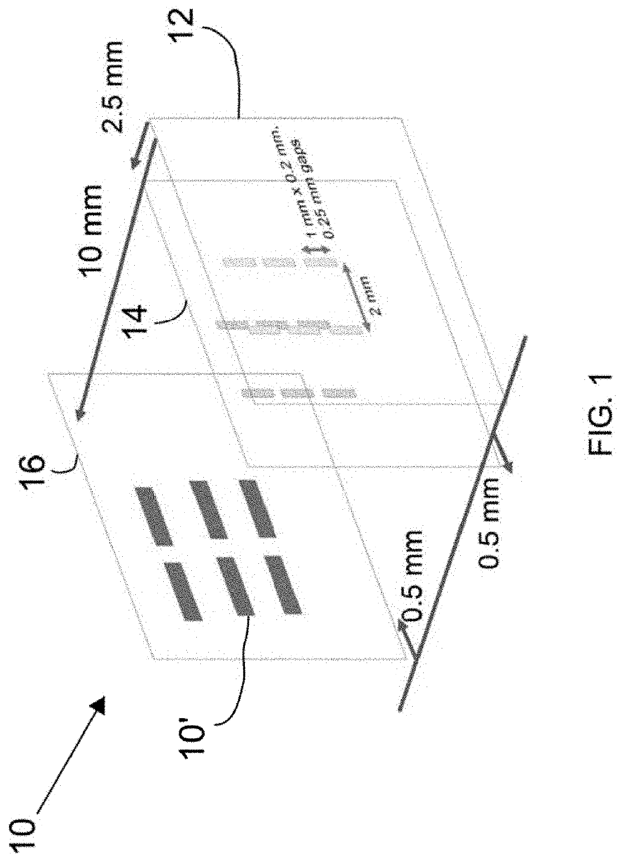
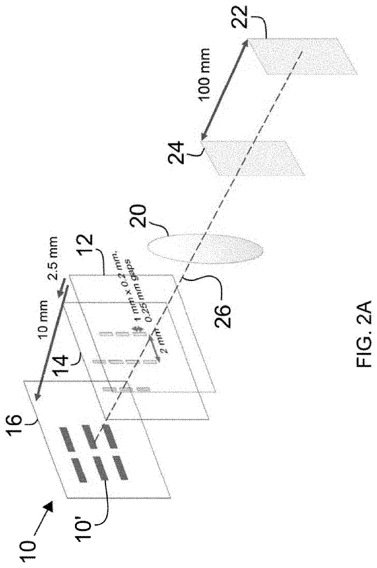
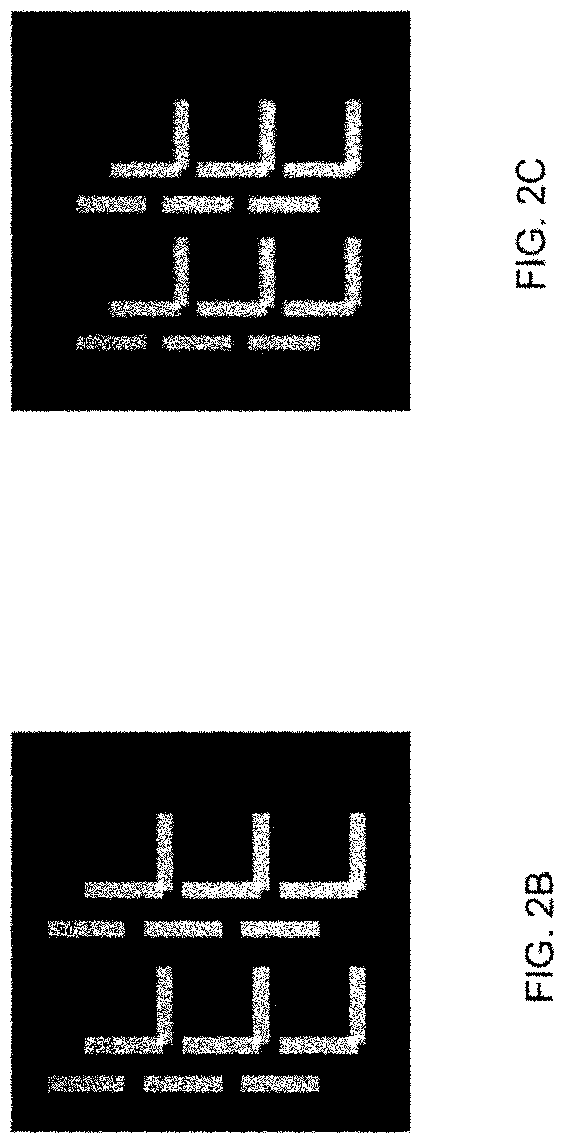
[0018]The invention combines two different hardware pieces. The first is an x-ray optic with a depth-of-field that is small compared to the object under investigation. Reflective Wolter type x-ray optics are one such design. These hollow optics have a relatively large collection efficiency and can be designed with a large field of view. The depth of focus, which is the distance over which a feature can be resolved along the imaging direction, is relatively small for these optics; it is typically small compared to the field of view. These optics have been used extensively in x-ray astronomy and in some cases for x-ray microscopy. The short depth of field distance is often considered a drawback to the design. However, when combined with a three-dimensional x-ray detector, it is possible to take advantage of the short depth of field to obtain additional information about the 3D structure of an object. One simple version of the 3D detector uses film. The x-rays are partially transmitted...


PUM

PropertyMeasurementUnit
depth resolutionaaaaaaaaaa
energyaaaaaaaaaa
sizeaaaaaaaaaa

Abstract

The invention utilizes one exposure without moving parts to provide multiple x-ray views of an object. It relies on a 3D detector, which can be a stack of film plates, and a specified focusing x-ray optic. The x-ray optic, discussed below, allows collection of x-rays from a localized volume, just like an ordinary optical lens, and the stacked film plate, or other 3D detector design, allows collection of the multiple focal plane information from one line of sight.

Description

CROSS-REFERENCE TO RELATED APPLICATIONS[0001]This application claims the benefit of U.S. Provisional Patent Application No. 62 / 585,241 titled “3-Dimensional X-Ray Imager,” filed Nov. 13, 2017, incorporated herein by reference.STATEMENT AS TO RIGHTS TO INVENTIONS MADE UNDER FEDERALLY SPONSORED RESEARCH OR DEVELOPMENT[0002]The United States Government has rights in this invention pursuant to Contract No. DE-AC52-07NA27344 between the United States Department of Energy and Lawrence Livermore National Security, LLC, for the operation of Lawrence Livermore National Laboratory.BACKGROUND OF THE INVENTIONField of the Invention[0003]The present invention relates to x-ray imaging, and more specifically, it relates to x-ray imaging of 3D objects.Description of Related Art[0004]The technical problem is obtaining three-dimensional structural information inside of objects in a manner which is nondestructive. The most often applied approach is conventional computed tomography where either the obj...

Claims


Application Information

Patent Timeline
Patent Type & Authority Patents(United States)
IPC IPC(8): G21K7/00A61B6/02G21K1/06G01N23/085
CPCG21K1/062G21K7/00A61B6/022G01N23/085G21K2201/062G01N23/04G01N2223/414G01N2223/50
Inventor KOZIOZIEMSKI, BERNARD J.IZUMI, NOBUHIKOVOGEL, JULIA K.PICKWORTH, LOUISA A. P.
Owner LAWRENCE LIVERMORE NAT SECURITY LLC
Why Eureka
Try Eureka