Device for transverse cutting of a web material and machine containing said device

a technology of transverse cutting and web material, which is applied in the direction of metal working apparatus, etc., can solve problems such as inaccuracy of cutting

Active Publication Date: 2020-08-18
FOSBER
View PDF18 Cites 2 Cited by
  • Summary
  • Abstract
  • Description
  • Claims
  • Application Information

AI Technical Summary

Benefits of technology

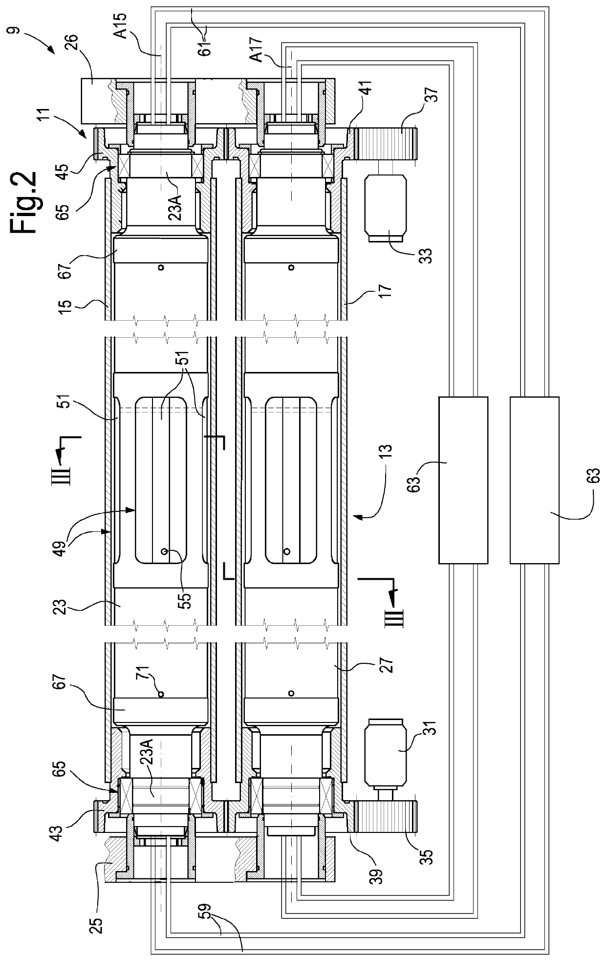
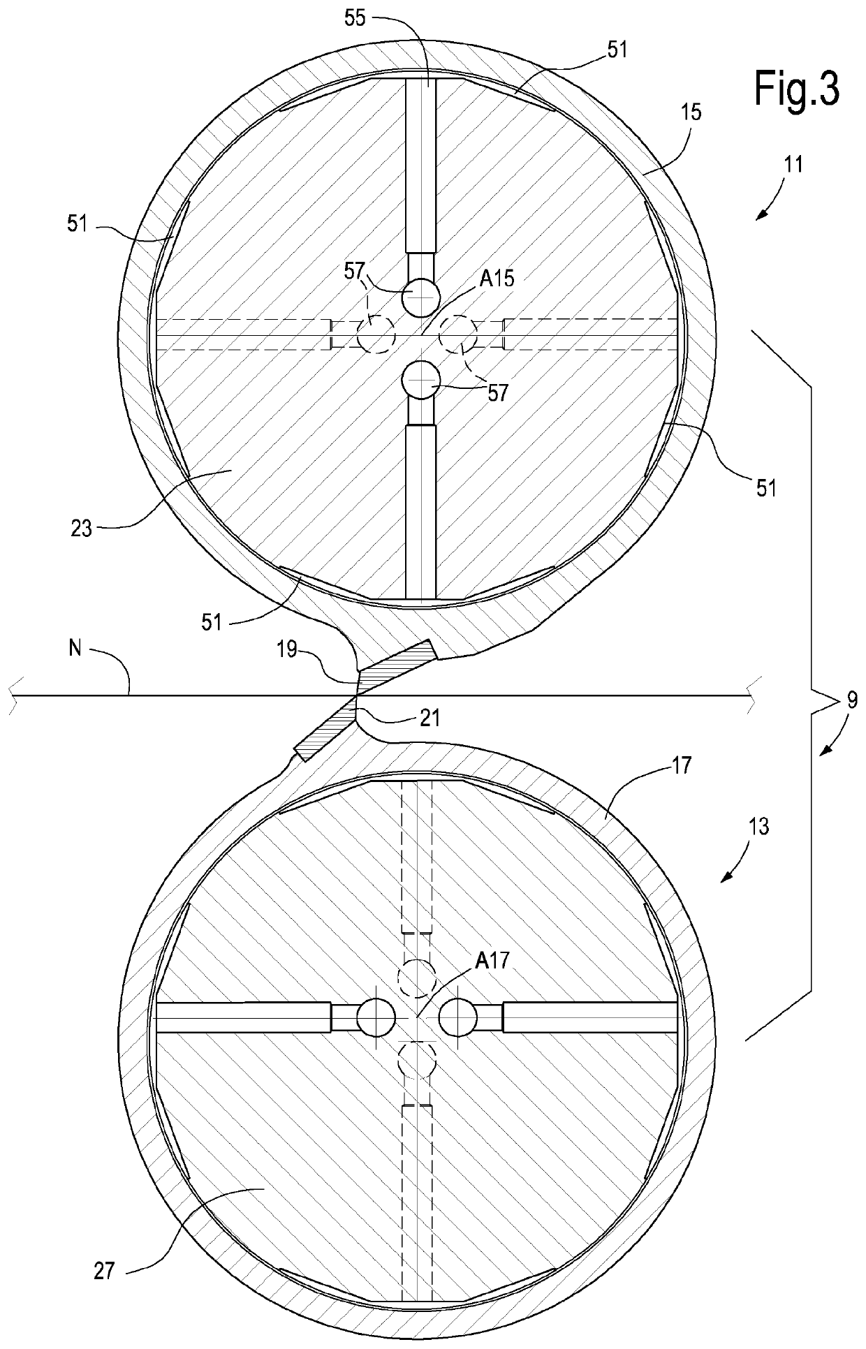
[0016]Thanks to the use of a central hydrostatic bearing, the difference between the inner diameter of the hollow roller and the outer diameter of the stationary shaft, onto which the hollow roller is supported, is minimal. In this way, given the same outer dimension of the hollow roller, it is possible to optimize the cross section of the stationary shaft and it is therefore also possible to reduce deformations to which the stationary shaft is subject. It is also possible to reduce vibrations in operation, this resulting in a better product and less wears, as well as in reduced noise.
[0023]The device can comprise a bearing fluid dispenser, configured to adjust the flow rate of the bearing fluid towards the hydrostatic pads, the dispenser being configured to vary the flow rate of bearing fluid towards at least one hydrostatic pad. In this way, it is possible to generate, on the hollow roller, a thrust having, for instance, a variable intensity and direction, to balance any deformation resulting from the load.
[0027]The use of rolling bearings instead of hydrostatic bearings can be advantageous, as it allows the hollow roller to remain in fixed position with respect to the stationary shaft even when there is no motion and the bearing fluid is not fed.

Problems solved by technology

This adjustment can be modified only by regulating the cam system again, and this is quite laborious.
Moreover, the existing shear machines are subject to thermal expansions resulting from the non-uniform heating of the cutting roller, and these thermal expansions can cause cut inaccuracies.

Method used


Image

  • Device for transverse cutting of a web material and machine containing said device
  • Device for transverse cutting of a web material and machine containing said device
  • Device for transverse cutting of a web material and machine containing said device

Examples


Embodiment Construction

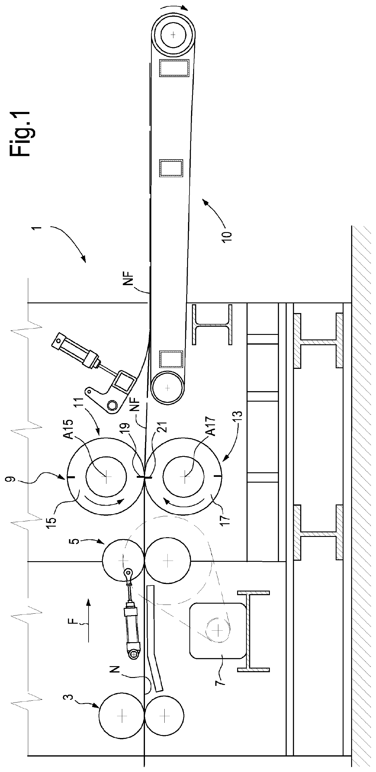
[0043]The following detailed description of the exemplary embodiments refers to the accompanying drawings. The same reference numbers in different drawings identify the same or similar elements. Additionally, the drawings are not necessarily drawn to scale. Also, the following detailed description does not limit the invention. Instead, the scope of the invention is defined by the appended claims.

[0044]Reference throughout the specification to “one embodiment” or “an embodiment” or “some embodiments” means that the particular feature, structure or characteristic described in connection with an embodiment is included in at least one embodiment of the subject matter disclosed. Thus, the appearance of the phrase “in one embodiment” or “in an embodiment” or “in some embodiments” in various places throughout the specification is not necessarily referring to the same embodiment(s). Further, the particular features, structures or characteristics may be combined in any suitable manner in one...


PUM

PropertyMeasurementUnit
speedaaaaaaaaaa
diameter D2aaaaaaaaaa
angleaaaaaaaaaa

Abstract

The device includes a hollow cutting roller with a blade attached to the outer surface of the hollow roller. A stationary shaft is also provided, arranged inside the hollow roller and coaxial therewith. The stationary shaft is connected to a supporting structure and the hollow roller is rotatably supported onto the stationary shaft. A motor drive is provided to rotate the hollow roller around the stationary shaft. The hollow roller is supported onto the stationary shaft by at least a hydrostatic bearing arranged in an intermediate position between the ends of the stationary shaft.

Description

TECHNICAL FIELD[0001]The present invention relates to devices for transverse cutting of a web material, for instance a cardboard strip, especially, but without limitation, corrugated cardboard, continuously fed along a feeding path.BACKGROUND ART[0002]In many industrial processes, it is necessary to cut a continuous web material, fed along a feeding path, into single sheets.[0003]This kind of cutting device is typically used in the production of cellulose sheets, for instance sheets of corrugated cardboard.[0004]Corrugated cardboard is produced continuously starting from reels of paper, from which at least three paper sheets are unwound and then glued together. Before being glued, the intermediate sheet is processed by means of a corrugator to form transverse flutes that are glued to the two outer sheets, or webs, forming the so-called liners of the finished corrugated cardboard. The corrugated cardboard can also comprise more than three sheets glued together, arranging corrugated s...

Claims


Application Information

Patent Timeline
Patent Type & Authority Patents(United States)
IPC IPC(8): B26D1/40B26D5/12B26D7/26B26D1/62
CPCB26D5/12B26D7/265B26D1/626B26D1/405Y10T83/4844Y10T83/4838B26D1/62B26D1/40
Inventor ADAMI, MAUROTOMELLERI, RAFFAELE
Owner FOSBER
Why Eureka
Try Eureka