Liquid material application apparatus and liquid material application method

a technology of liquid material and application apparatus, which is applied in the direction of programming control, instruments, coatings, etc., can solve the problems of relative moving speed between the dispenser and the worktable, and achieve the effect of reducing the laborious task of programming to be prepared by the operator

Active Publication Date: 2020-09-29
MUSASHI ENG INC
View PDF58 Cites 1 Cited by
  • Summary
  • Abstract
  • Description
  • Claims
  • Application Information

AI Technical Summary

Benefits of technology

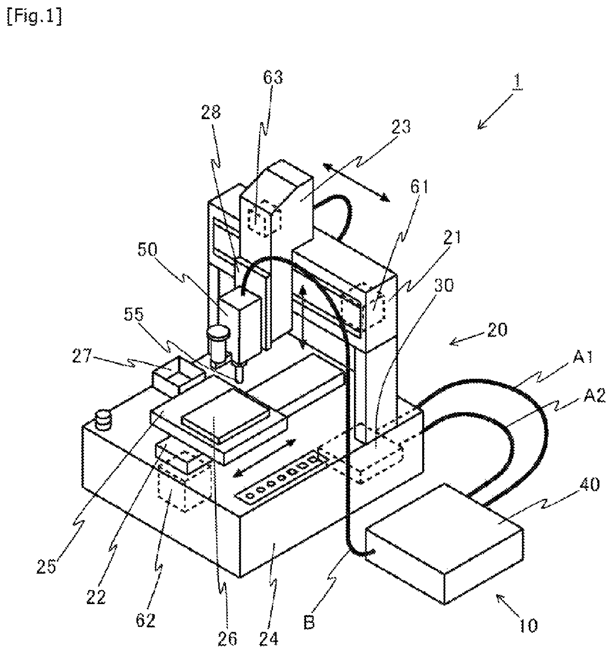
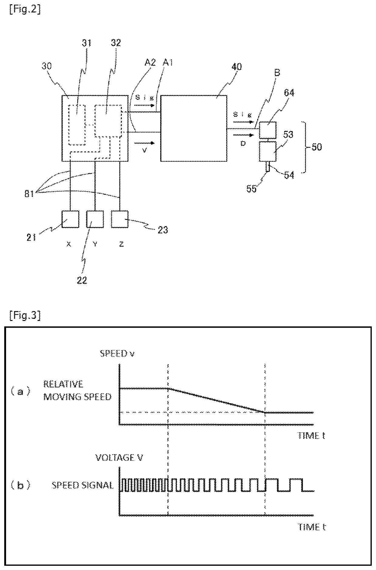
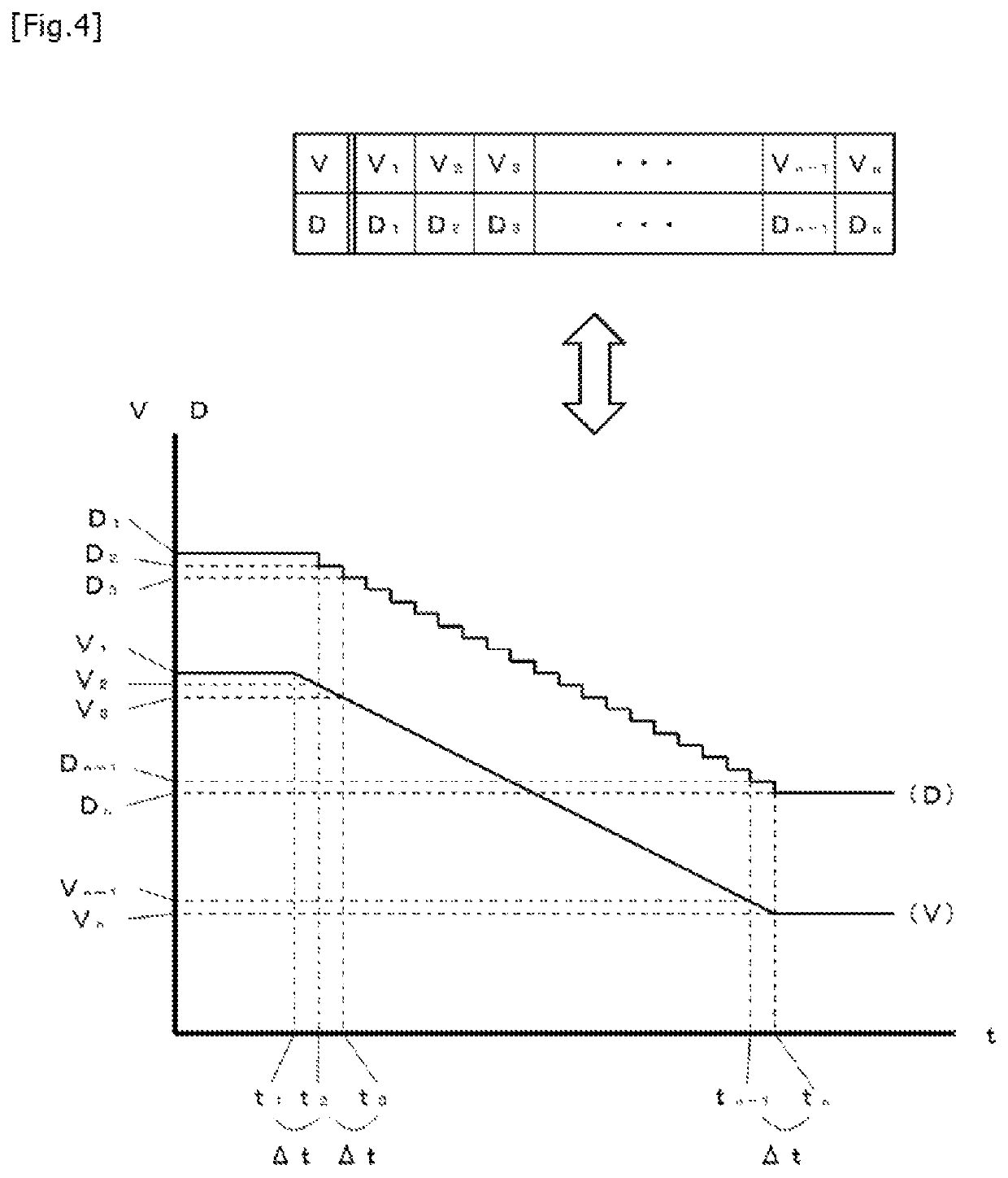
[0034]According to the present invention, the first mode discharge control of changing the discharge amount per unit time of the liquid material, which is discharged from the discharge head, depending on the relative moving speed between the discharge head and the workpiece and the second mode discharge control of operating the discharge head to discharge the liquid material in a predetermined discharge amount per unit time regardless of the relative moving speed can be executed in a switchable manner in accordance with the application program. Hence application work can be properly performed while laborious task for programming to be prepared by an operator is reduced.

Problems solved by technology

However, when a line drawing application is performed for the application pattern including a corner portion, a problem occurs in that a relative moving speed between the dispenser and the worktable is changed and a line width of a drawn application line varies in the corner portion (i.e., a problem that, in spite of desiring a line to be applied in the corner portion in the same width as that in a linear portion as illustrated in FIG. 10(A), the line in the corner portion becomes wider than in the linear portion as illustrated in FIG. 10(B) due to change of the relative moving speed between the dispenser and the worktable in the corner portion).

Method used


Image

  • Liquid material application apparatus and liquid material application method
  • Liquid material application apparatus and liquid material application method
  • Liquid material application apparatus and liquid material application method

Examples


example 1

[0102]First, the series of application works illustrated in FIG. 6 is described. In the series of application works illustrated in FIG. 6, the line drawing application of drawing a predetermined application pattern on the workpiece 26 and the dumping application of discarding the liquid material into the dumping discharge area 27 are performed alternately. Prior to starting the series of application works, the operator initially sets (programs), in the dispense controller 40, the discharge amount per unit time in a square application pattern illustrated in FIG. 6 and the discharge amount per unit time in the dumping discharge area 27.

[0103]The line drawing application for the square application pattern is performed in the first mode discharge control. The operator can set the first mode discharge control, by way of example, as follows. The operator repeatedly adjusts the discharge control amount D such that the line width of the application line becomes a desired line width Wa at a ...

example 2

[0120]The operation of the application apparatus 1 in a series of application works illustrated in FIG. 7 will be described below. In the series of application works illustrated in FIG. 7, a linear portion JK in a square application pattern illustrated in FIG. 7 is drawn in a larger line width than the other portions. Furthermore, in the series of application works illustrated in FIG. 7, the dumping application is not performed, and the application operation for the square application pattern illustrated in FIG. 7 is repeated continuously. In the following, the series of application works illustrated in FIG. 7 is described mainly about points different from the series of application works illustrated in FIG. 6.

[0121]In the series of application works illustrated in FIG. 7, because the linear portion JK does not include the corner portion, the dispense head 50 can be relatively moved at the constant relative moving speed V in the linear portion JK. Accordingly, the operator sets the ...

example 3

[0127]A series of application works illustrated in FIG. 8 will be described below. In the series of application works illustrated in FIG. 8, the line drawing application for a square application pattern and the spot application for a spot pattern made up of three spots are performed alternately without performing the dumping application.

[0128]In the series of application works illustrated in FIG. 8, the discharge control in the line drawing application for the square application pattern is performed in accordance with the first mode discharge control, and the discharge control in the spot application is performed in accordance with the second mode discharge control. Thus, the operator can set the application program for the robot controller 30 such that the discharge control in the line drawing application for the square application pattern is performed in accordance with the first mode discharge control, and that the discharge control in the spot application is performed in accorda...


PUM


Abstract

A liquid material is discharged in a constant amount per unit time regardless of a relative moving speed. The liquid material application apparatus includes a discharge head, a robot moving the discharge head relative to a workpiece, a movement control unit controlling relative movement of the discharge head and the workpiece, and a discharge control unit controlling an operation of discharging a liquid material from a discharge head, wherein the discharge control unit executes, in a switchable manner in accordance with an application program, first mode discharge control of changing a discharge amount of the liquid material, which is discharged from the discharge head per unit time, depending on a relative moving speed between the discharge head and the workpiece, and second mode discharge control of operating the discharge head to discharge the liquid material in a predetermined discharge amount per unit time regardless of the relative moving speed.

Description

TECHNICAL FIELD[0001]The present invention relates to a liquid material application apparatus and a liquid material application method for use in performing a desired line drawing application (also broadly called a drawing application) on a workpiece while a discharge head and the workpiece are moved relative to each other.BACKGROUND ART[0002]A discharge device called a dispenser is used in many cases to apply a liquid material along a predetermined pattern in a process of manufacturing electronic devices. The dispenser is widely used in manufacturing various devices ranging from large-sized devices to small-sized devices. For instance, the dispenser is used in a step of linearly applying a phosphor or an adhesive onto a flat panel display represented by a liquid crystal or organic EL display, or in a step of linearly applying an adhesive for fixing a smartphone cover along an outer periphery of the cover.[0003]Application work using the dispenser is performed by discharging a liqui...

Claims


Application Information

Patent Timeline
Patent Type & Authority Patents(United States)
IPC IPC(8): B05B12/12B05B13/04B05D1/02
CPCB05B13/0431B05B12/126B05D1/02B05C5/00B05C11/1002B05C11/10B05D1/26H01L21/02307B05C5/0225B05C5/0216G05B2219/45065B05C11/1005B05B12/084G05B2219/45B05C11/1015
Inventor IKUSHIMA, KAZUMASA
Owner MUSASHI ENG INC
Why Eureka
Try Eureka