Unloading knee brace apparatus

a knee brace and knee joint technology, applied in the field of orthopaedic knee braces, can solve the problems of reducing the amount of force on the joint, reducing reducing the effectiveness of preventing and reducing pain, so as to reduce the amount of pain, reduce friction in the knee area, and effectively unload a significant amount of force within the knee.

Active Publication Date: 2020-10-20
ICARUS MEDICAL LLC
View PDF23 Cites 4 Cited by
  • Summary
  • Abstract
  • Description
  • Claims
  • Application Information

AI Technical Summary

Benefits of technology

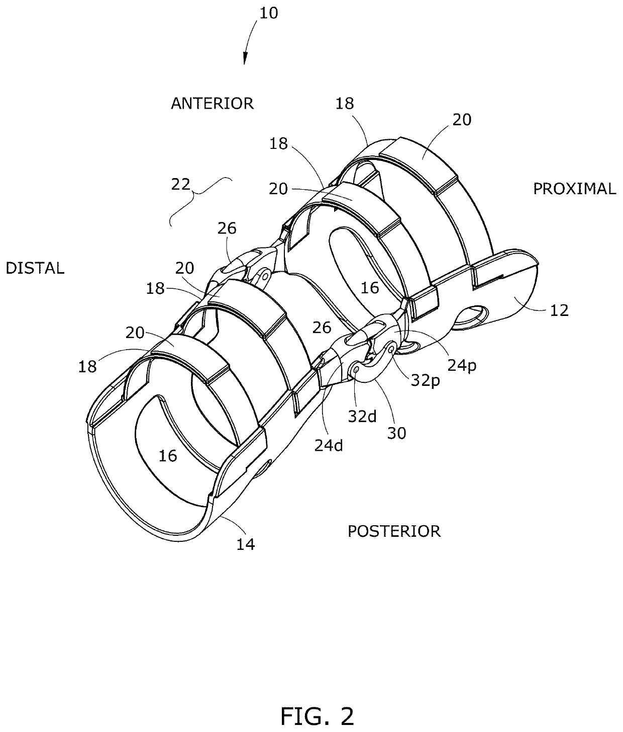
[0014]Various embodiments of the present disclosure comprise a novel type of unloading knee brace that has been designed to reduce the amount of pain that patients experience as a result of knee OA. The knee braces and hinge assemblies disclosed herein generate a force opposing the bending or contracting/flexion of the knee joint. The braces can be suitable for either a knee joint or elbow joint, however the knee joint will only be discussed here in detail such that one of skill in the art could readily apply this disclosure to an elbow brace. The brace effectively unloads a significant amount of force within the knee by using a high-tension resistance mechanism described herein, and by distributing the force to other areas of the body. This results in reduced friction in areas of the knee afflicted with OA, and therefore less pain. The embodiments described herein all...

Problems solved by technology

Unloading braces have been used as inexpensive therapeutic solutions for knee OA; however, they are largely ineffective in preventing and reducing pain.
The joint itself, including its underlying cartilage, can only support a certain amount of force before the cartilage begins to wear away, and unloading knee braces decrease the amount of force on the joint.
In addition, up to 10 percent of the U.S. population suffers from pain and loss of function from patella arthritis and cartilage wear.
Other surgical procedures such as articular cartilage restorat...

Method used


Image

  • Unloading knee brace apparatus
  • Unloading knee brace apparatus
  • Unloading knee brace apparatus

Examples


— embodiments 1-4

Method of Use—Embodiments 1-4

[0131]In the various embodiments of the present disclosure, the amount of weight unloading (or resistance or tension generated in the brace) can readily be tailored to the user based on their size, weight, and desired athletic performance. Braces based on this concept have promise of being lightweight, robust, of a narrow side profile, and well-fitting to users. Unlike braces in the prior art, those disclosed herein can be narrow and lightweight to be worn under clothing, which is usually not possible for athletic performance braces. For these reasons, the brace can be ideal for a range of injury types and severity.

[0132]The various embodiments of the knee brace of the present disclosure can be used, by way of non-limiting examples: prophylactically to prevent injury; to reduce joint pain (e.g. during physical exercise or athletic competition); to rehabilitate existing injuries; post-operatively (high tension braces to immobilize the joint to a comfortab...


PUM


Abstract

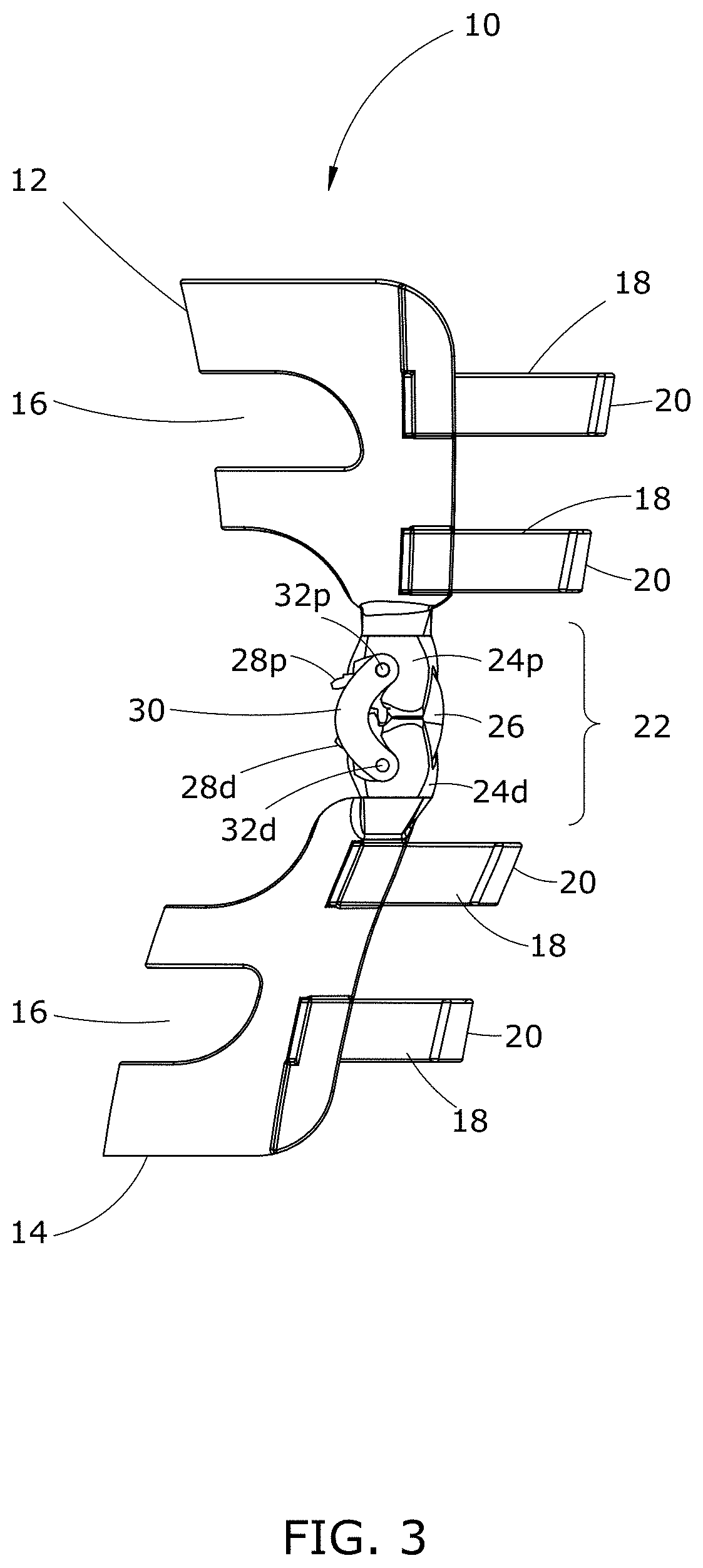
An adjustable tension knee brace for unloading weight from a knee joint afflicted with osteoarthritis, thus reducing pain and improving mobility, comprising: an upper and lower rigid posterior portion, anterior straps, and a tension adjustable geared hinge assembly. Four embodiments are disclosed of hinge assemblies useable with the knee brace, or other types of braces. The hinge assemblies comprise: two subunits housing intermeshed gears, and at least one elastic band extending between the hinge subunits over a cam surface above the gears. In three embodiments, U-shaped connectors secure the subunits and gears together, and the subunits may comprise a user mechanism that adjusts the elastic band's tension and thus the amount of weight unloaded, then releases it. Another embodiment comprises a core bracket to protect the band(s) and a mechanism to compress the elastic band at various points to increase the amount of tension, and with a quick release mechanism.

Description

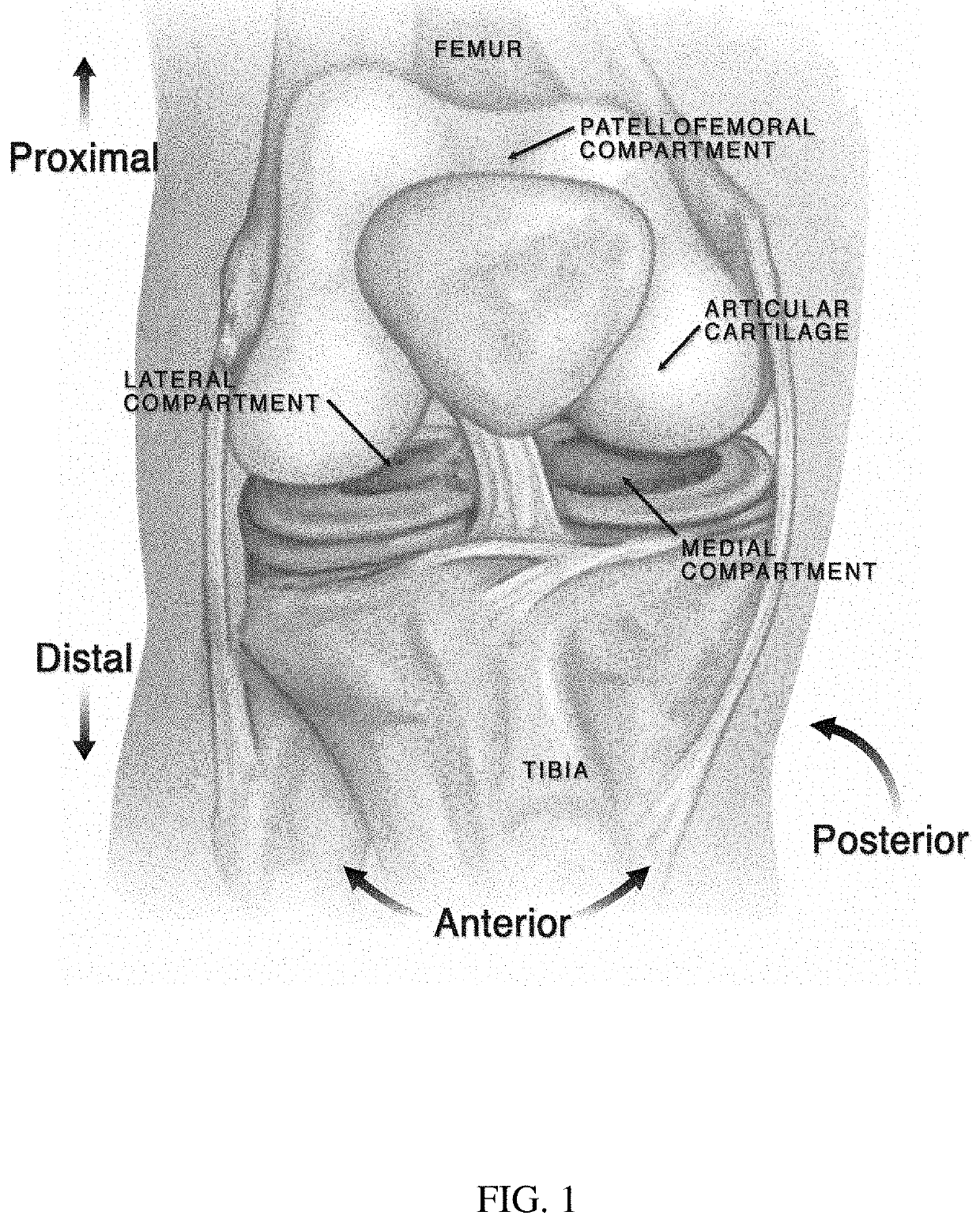
PRIORITY CLAIM[0001]The present application claims priority to and benefit from U.S. Provisional Patent Application No. 62 / 331,315 filed on May 3, 2016, the entire contents of which are hereby expressly incorporated by reference.TRADEMARKS DISCLAIMER[0002]The product names used in this document are for identification purposes only. All trademarks and registered trademarks are the property of their respective owners.FIELD OF THE INVENTION[0003]The present invention disclosed herein relates generally to orthosis knee braces to relieve pain by unloading the joint by providing extension assistance and / or by redistributing the weight on the knee joint.BACKGROUND OF THE INVENTION[0004]Osteoarthritis (OA) is a degenerative joint disease characterized by chronic deterioration of the joint cartilage and the underlying bone. In particular, the patellofemoral compartment is one of the most frequent points of knee pain. Unloading braces have been used as inexpensive therapeutic solutions for kn...

Claims


Application Information

Patent Timeline
IPC IPC(8): A61F5/01
CPCA61F5/0125A61F2005/0165A61F2005/0139
Inventor JOHNSON, DAVID T.
Owner ICARUS MEDICAL LLC
Why Eureka
Try Eureka