Space rocket monitoring system for greenhouse gas emissions

Active Publication Date: 2020-10-27
JAIN RISHI IYER
View PDF0 Cites 1 Cited by
  • Summary
  • Abstract
  • Description
  • Claims
  • Application Information

AI Technical Summary

Benefits of technology

[0007]The invention was inspired, in part, by the insight that progress on controlling greenhouse gas emissions could be advanced if more people, in particular high school and college students

Problems solved by technology

Global warming is a major ongoing ecological catastrophe, which over the next several generations is likely to undermine the health and safety of millions and perhaps billions of individuals.
The problem is primarily caused by greenhouse gases, such as carbon dioxide (CO2) and methane, which are produced by the burning of fossil fuels, agriculture, and other modern industrial processes.
These cause the earth to warm, and ice caps to melt, resulting in a rise in sea levels, loss of valuable habitable

Method used


Image

  • Space rocket monitoring system for greenhouse gas emissions
  • Space rocket monitoring system for greenhouse gas emissions
  • Space rocket monitoring system for greenhouse gas emissions

Examples


Embodiment Construction

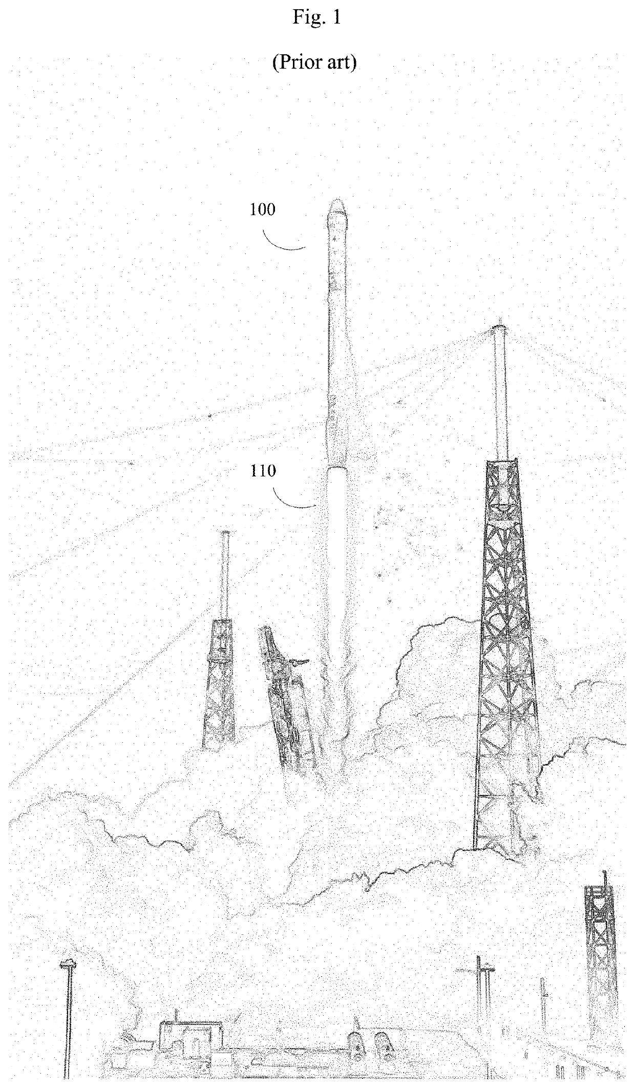
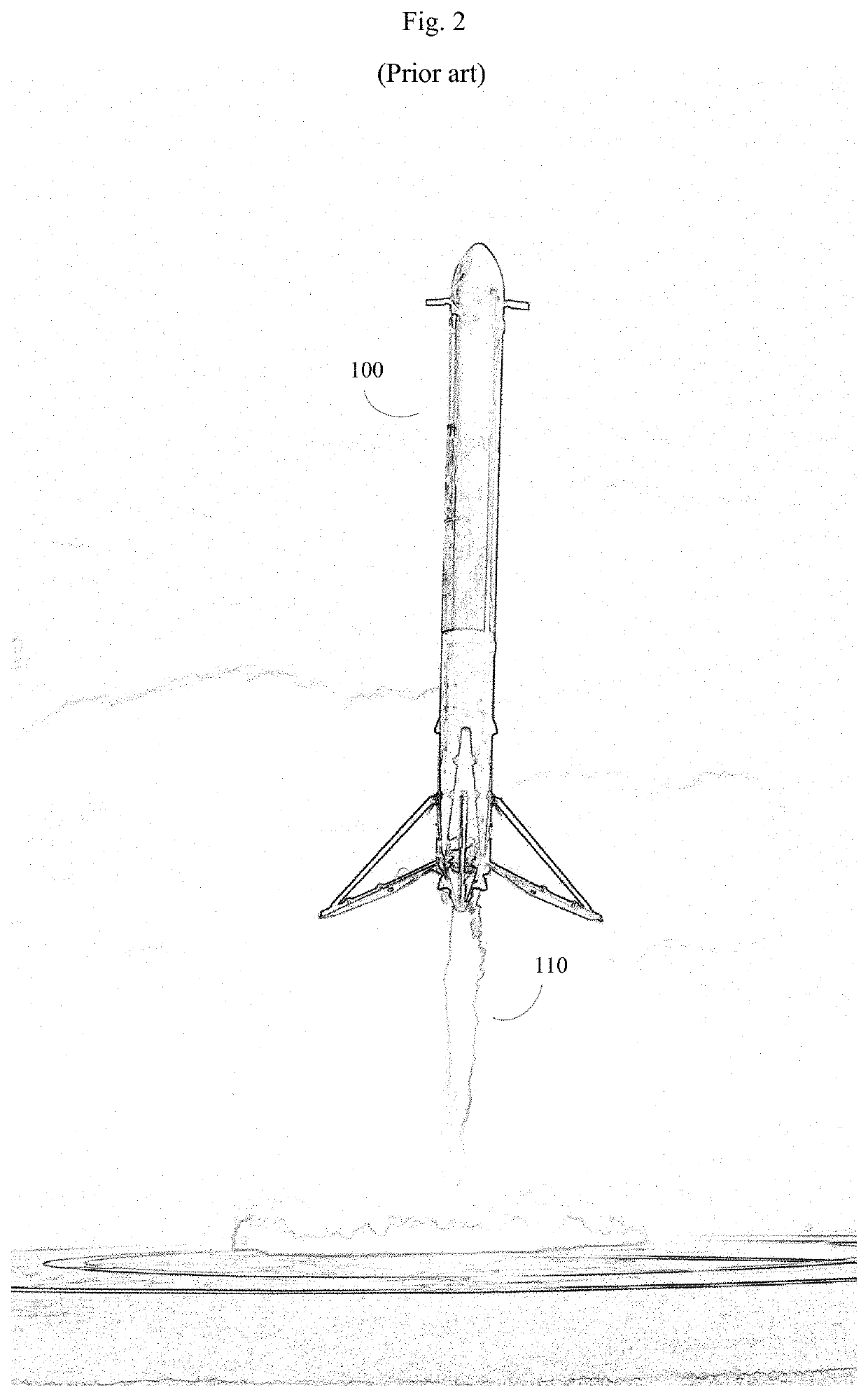
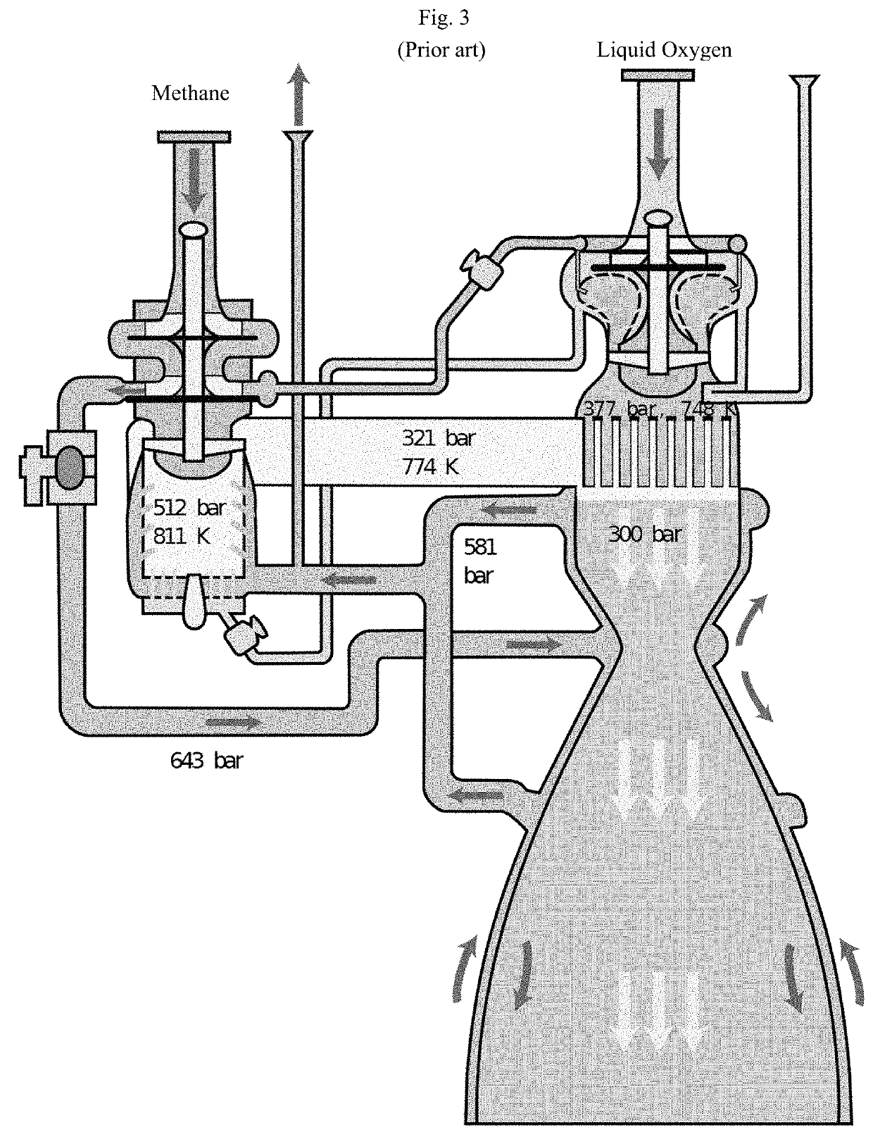
[0029]The invention can be used to monitor greenhouse gas emissions during both rocket assents (takeoffs) and, for the latest reusable rocket boosters, rocket descents (landings) as well. Although in disclosure, SpaceX Falcon 9 rockets and Raptor engines have been used as examples, these examples are not intended to be limiting.

[0030]FIG. 1 shows an image of a rocket (here a SpaceX Falcon 9) on initial takeoff. Typically each rocket (100) has certain distinctive design features, which can be used to identify the rocket either visually, or by use of computerized vision systems. Note the distribution of the rocket exhaust plume (110). On takeoff, rocket engines are often throttled to different efficiency settings depending on the phase of the flight. For example, it is common to throttle rocket engines back while passing through the region of maximum dynamic pressure. Rocket engines also may be throttled to different extents depending on altitude, payload, presence or absence of side ...


PUM


Abstract

System and method of implementing a Space Rocket monitoring system for greenhouse gas emissions during rocket flight, employing smartphone video cameras equipped with custom lens attachments, image deconvolution software, machine vision software, and the Tsiolkovsky Rocket Equation. The smartphone is equipped with custom optical lens attachments including a periscope that improves spatial separation (parallax) between camera images and a spectroscope that disperses incoming light from the combustion characteristics of the rocket exhaust according to wavelength and frequency of the light. A combination of image deconvolution software and machine vision software analyzes the images, and matches with existing rocket databases (which may be on remote servers), to identify key rocket characteristics. These are used, in the Tsiolkovsky Rocket Equation to compute rocket fuel expenditures. The software computes greenhouse gas emissions and presents the results using a graphical user interface that presents rocket flight images and corresponding analytics.

Description

BACKGROUND OF THE INVENTIONField of the Invention[0001]This invention is in the field of methods and technologies to monitor greenhouse gas emissions.Description of the Related Art[0002]Global warming is a major ongoing ecological catastrophe, which over the next several generations is likely to undermine the health and safety of millions and perhaps billions of individuals. The problem is primarily caused by greenhouse gases, such as carbon dioxide (CO2) and methane, which are produced by the burning of fossil fuels, agriculture, and other modern industrial processes. These cause the earth to warm, and ice caps to melt, resulting in a rise in sea levels, loss of valuable habitable and agricultural land, increase in deserts and unacceptably hot regions, and diminished agricultural output.[0003]With the advent of cost-effective alternative energy sources, such as solar energy and wind energy, and advances in battery technology, technological solutions for greenhouse gas emissions are...

Claims


Application Information

Patent Timeline
IPC IPC(8): H04M1/725G06K9/00G01S19/47G01N33/00B64G3/00H04N5/247H04N7/18H04M1/72403
CPCB64G3/00G01N33/0036H04N7/18G01S19/47H04N5/247H04M1/725G06K9/00671H04M2250/52H04M1/72403B64G1/002B64G1/401G06V20/194G06V20/52G06V10/147G06V10/58H04N23/50H04N23/80H04N23/90G06V20/20
Inventor JAIN, RISHI IYER
Owner JAIN RISHI IYER
Why Eureka
Try Eureka