
Atom-based electromagnetic field sensing element and measurement system

Active Publication Date: 2020-11-03
RYDBERG TECH INC
View PDF30 Cites 14 Cited by
  • Summary
  • Abstract
  • Description
  • Claims
  • Application Information

AI Technical Summary

Benefits of technology

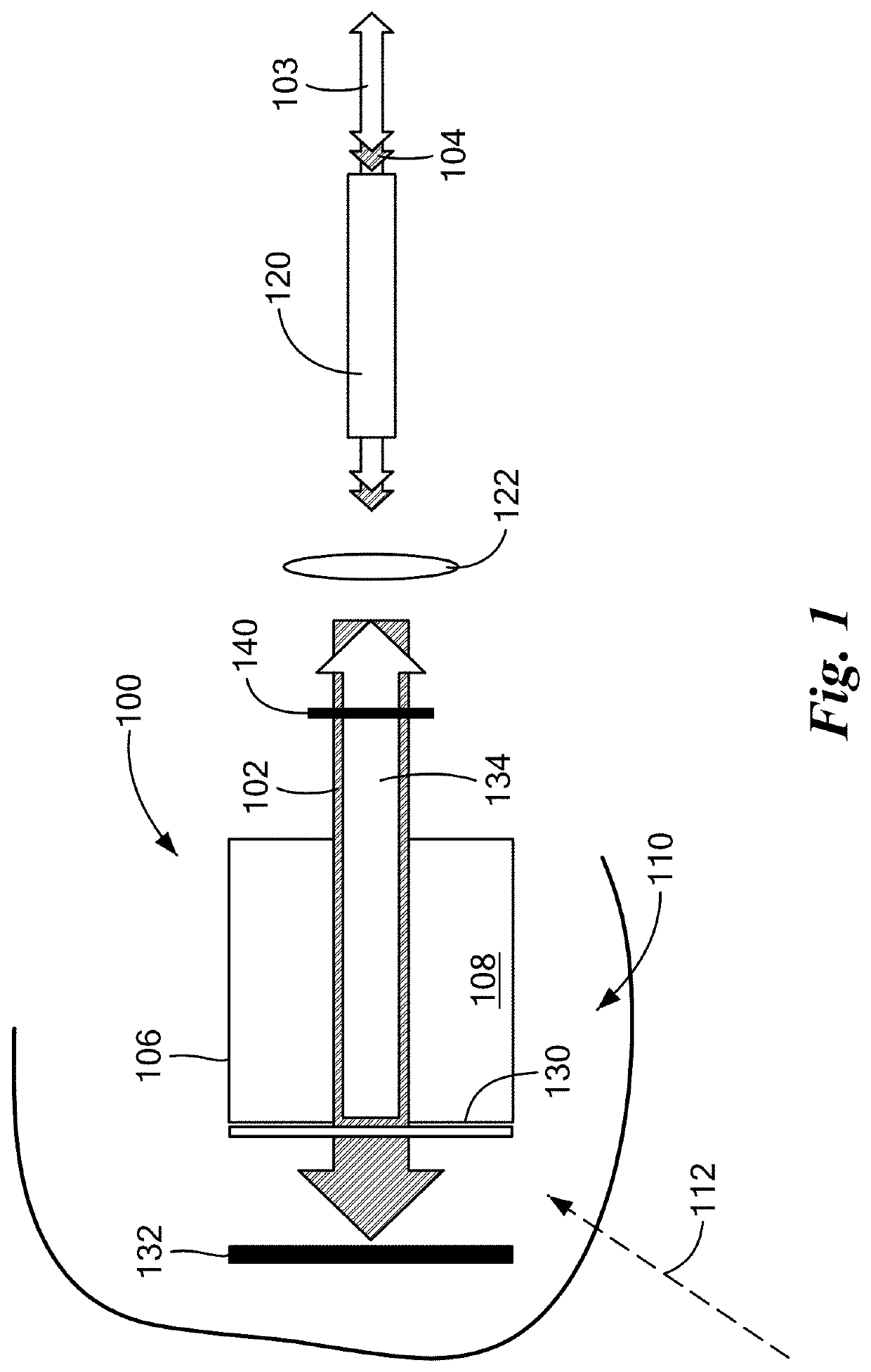
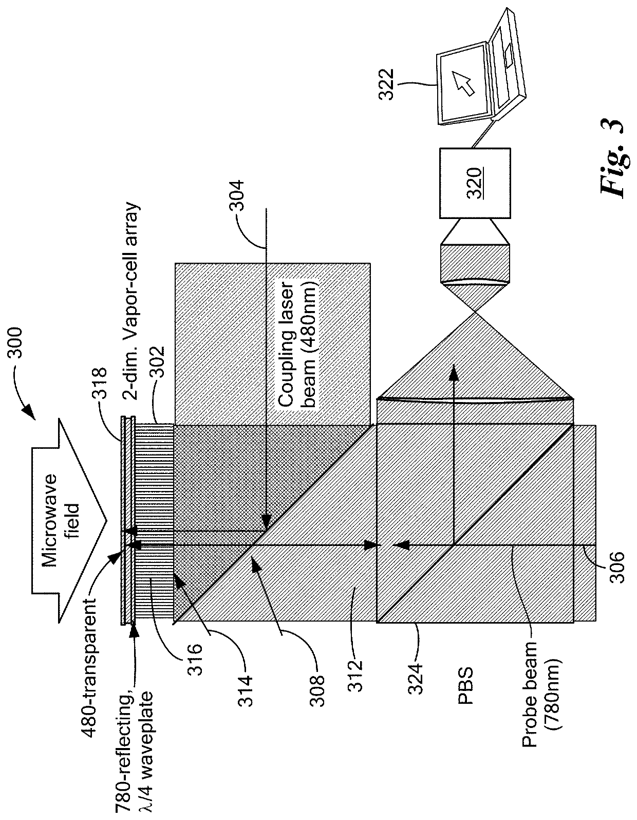
The present invention provides a method for sensing or measuring a first electromagnetic field by exciting atoms of a gas in a distribution of Rydberg states and measuring a spectral feature of the gas. This method can be used to detect and measure various parameters of the electromagnetic field, such as its amplitude and phase. The invention also provides a monolithic sensor that includes an atomic vapor and a source of excitation for exciting the atoms into a distribution of Rydberg states. The sensor can be used to detect and measure the electromagnetic field in a variety of applications, such as in atomic vapor cells and in the presence of other electromagnetic fields. The invention also provides a unilaterally-coupled monolithic sensor that includes a dielectric enclosure and a source of excitation for generating an excitation beam and a probe beam. The sensor can be used to detect and measure the electromagnetic field in a variety of ways, such as by measuring the spectral feature of the gas or by using optical elements to couple the excitation and probe beams.

Problems solved by technology

Electromagnetically induced transparency (EIT) is a quantum interference process in which two excitation pathways in a three-level atomic system destructively interfere and produce an increase in the transmission of a probe laser beam.
No method of Rydberg spectroscopy hitherto suggested, however, has ever been suited to measuring a phase of an electromagnetic field (relative to a fiducial phase reference).
(1) Low sensitivity; the highest field sensitivity demonstrated to date is at the 1 mV / m level, limited primarily by EIT linewidths. Furthermore, this sensitivity level has only been achieved by monitoring small changes in the EIT peak line shape. Unlike measuring Rydberg energy-level spitting directly, where the field is traceable to fundamental constants and invariable atomic parameters, extracting the RF electric field from a detailed EIT line shape analysis requires a relatively complex model that depends on experimental parameters such as laser beam powers and vapor pressures, thereby precluding an absolute field measurement and making it unreliable in everyday operation. To date, the most sensitive measurement sensitivity in the prior art, a shot-noise limited sensitivity of about 3 μV / cm / Hz1 / 2, has been demonstrated in work of Kumar et al., “Rydberg-atom based radio-frequency electrometry using frequency modulation spectroscopy in room temperature vapor cells,” Opt. 25, 284263 (21 Jan. 2017), an improvement of half an order of order of magnitude over sensitivity reported earlier in Fan et al., “Effect of Vapor Cell Geometry on Rydberg-Atom-Based Measurements of Radio-Frequency Electric Fields,” Phys. Rev. Appl., 044015 (2015), both of which papers are incorporated herein by reference. The latter work exploits minute RF-induced EIT enhancement of Rydberg-EIT lines by weak, resonant RF fields, a method expected to be somewhat unreliable in everyday field-measurement operation, because the minute changes depend on many details, such as laser powers and cell pressure. More robust means to enhance the sensitivity are desired.
(2) Inability to measure RF fields over a continuous frequency range. In weak RF fields, the method is limited to measurements of RF fields that are resonant with dipole-allowed transitions between Rydberg states. Weak RF fields that are off- and far-off-resonance from any transition cannot be measured easily, if at all.
(3) RF polarization measurements currently require a complex analysis of the atomic spectra.
(4) All prior art Rydberg-EIT measurements have necessarily been field amplitude measurement, while information on the phase of the RF field has never been possible to obtain in part because of physical constraints discussed herein.
(5) The form factor of measurement apparatuses used to date for Rydberg EIT measurements have necessarily require large components, assemblies that are not portable or have a large dielectric footprint, thereby precluding the ability to perform measurements in many practical applications or to be integrated into existing RF measurement and transmission systems.
(6) Prior to the invention described herein below, Rydberg EIT techniques have served solely for measurement of coherent fields. Prior methods were incapable of measuring either incoherent fields or noise.
This aspect has, to-date, posed a challenge in the implementation of Rydberg EIT in vapor cells in practical sensor designs for applications because it requires the laser beams to enter and exit the cells from opposing sides, either via free-space propagation or optical fibers on either side of the cell.
This can lead to a sensor head with a large dielectric footprint and size that is undesirable for measurement applications.
Further, for extensions to multi-pixel sensor arrays, entry of the optical beams from opposite sides of the cells can limit pixel packing density and resolution achievable in an array.
While most of the matter in the observable universe exists in the plasma state, measurement or inference of characteristics of an electric field within a region of plasma poses particular challenge to science unless collective motion of the plasma may be observed, or unless a physical probe can be inserted into the plasma.
While existing methods afford passive non-intrusive measurements, they may also require a priori knowledge of the optical absorption or emission spectra of the plasma constituents.
This can make it difficult to distinguish collective plasma phenomena of interest from few-body processes involving constituent plasma particles in the diagnostic readout.
Along these lines, some plasmas are expected to have emission profiles at frequencies and emission strengths that are difficult to detect using conventional detectors and spectrometers.
Weak IR emissions from vibrational transitions in plasma constituents, for example, may in some instances provide useful information but detectors required for measuring these low IR intensity levels have not been readily available.
This can pose a significant drawback in fundamental plasma studies, where the nature of the plasma is itself the subject of study.

Method used


Image

  • Atom-based electromagnetic field sensing element and measurement system
  • Atom-based electromagnetic field sensing element and measurement system
  • Atom-based electromagnetic field sensing element and measurement system

Examples


Embodiment Construction

Definitions

[0093]The following terms shall have the meanings indicated, unless otherwise dictated by context:

[0094]Certain embodiments of the present invention relate to an atom-based field sensing element that may also be referred to herein, synonymously, as a “sensing element,” a “field sensing element,” and as a “sensor.”

[0095]“Conditioning” shall, herein and in any appended claims, refer to the confinement, guiding, manipulation, or filtering of an electromagnetic field or a physical attribute of the EM field including its mode, electric field amplitude, polarization, frequency, phase, and spectral content.

[0096]The term “enhancement,” as it refers to an electromagnetic wave, shall be defined as the conditioning of that electromagnetic wave in such a manner as to increase the value of any physical attribute of the electromagnetic wave.

[0097]A “monochromatic field” shall refer either to a static field or to an electromagnetic field characterized by a range of frequencies no great...


PUM


Abstract

Methods and apparatus for sensing or measuring an electromagnetic field. The method entails excitation into a distribution of Rydberg states of atoms of a gas occupying a test volume coextensive with the electromagnetic field. Transmission along a path traversing the test volume of at least one probe beam of electromagnetic radiation is measured at one or more frequencies overlapping a spectral feature, and a physical characteristic of the electromagnetic field is derived on the basis of variation of the spectral feature. In various embodiments, the electromagnetic field may be place in interferometric relation with another electromagnetic field. Time-varying electric field amplitude, frequency, phase and noise spectral distribution may be measured, and thus AM and FM modulated fields, as well as magnetic fields of about 1 Tesla. The apparatus for measuring the electromagnetic field may be unilaterally coupled to a probe field and detector or array of detectors.

Description

[0001]The present application claims the priority of U.S. Provisional Application No. 62 / 607,034, filed Dec. 18, 2017, and of U.S. Provisional Application No. 62 / 727,764, filed Sep. 6, 2018. Both of the foregoing applications are incorporated herein by reference.[0002]This invention was made in part with Government support under Contract No. W911NF-17-C-0007, awarded by the Defense Advanced Research Projects Agency (DARPA) and the US Army. The Government may have rights in some aspects of the invention.FIELD OF INVENTION[0003]The present invention relates to an atom-based field sensing element and measurement system and methods, and, more particularly, to an element, system and methods that employ Rydberg atoms to measure, receive or image RF field amplitude, polarization, or phase, modulated RF signals, incoherent RF or RF noise, and to perform continuous-frequency RF field detection.BACKGROUND OF THE INVENTION[0004]Atoms with a quasi-free electron in a high-lying Rydberg state (ch...

Claims


Application Information

Patent Timeline
Patent Type & Authority Patents(United States)
IPC IPC(8): G01V3/00G01R29/08
CPCG01R29/0878G01R33/032G01R29/0892G01R29/0885
Inventor ANDERSON, DAVID A.RAITHEL, GEORG A.PARADIS, ERIC G.SAPIRO, RACHEL E.
Owner RYDBERG TECH INC
Learn More