Optical fibers and optical systems comprising the same

a technology of optical fibers and optical systems, applied in the field of optical fibers, can solve the problems of large amount of bessel beams generated by optical systems that are bulky in free space, and low alignment tolerance and high cost, and achieves low alignment tolerance, high cost, and flexible

Active Publication Date: 2020-11-10
CORNING INC
View PDF10 Cites 2 Cited by
  • Summary
  • Abstract
  • Description
  • Claims
  • Application Information

AI Technical Summary

Benefits of technology

[0072]One advantage of the optical fibers described herein is that these fibers can be used to convert conventional Gaussian beam into Bessel beam that is suitable for many applications, such as laser processing, laser cutting, and optical imaging.
[0073]A described above, Bessel beams is often generated using optical systems that are bulky and have low alignment tolerances and high cost. One advantage of the optical fibers and the optical systems described herein is that they enable some applications, such as remote laser processing and portable instruments. Replacing bulk optic components with optical fiber will provide more flexible and easily deployable instrumentation. For many applications, a fiber optic system for both laser delivery and beam shaping offers advantages of lower loss and better stability than what is available with conventional systems.

Problems solved by technology

However, free-space optics systems are bulky and have low alignment tolerances and high cost.
A described above, Bessel beams is often generated using optical systems that are bulky and have low alignment tolerances and high cost.

Method used


Image

  • Optical fibers and optical systems comprising the same
  • Optical fibers and optical systems comprising the same
  • Optical fibers and optical systems comprising the same

Examples


examples

[0344]The embodiments described herein will be further clarified by the following examples.

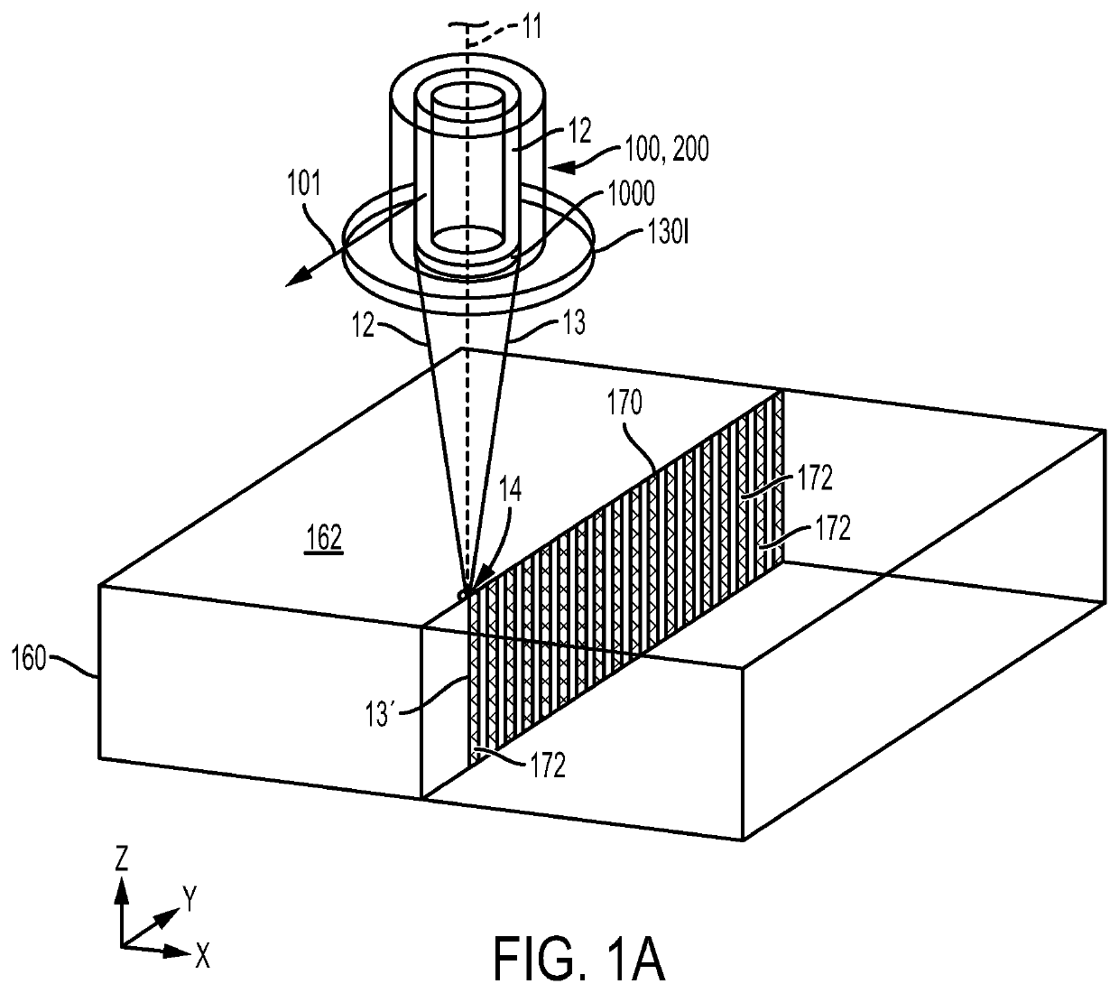
[0345]A summary of radii and relative refractive indices for five examples (Examples 1-5) of the optical fiber 100 depicted in FIGS. 1A and 5A-8A are shown in Table 1A below.

[0346]

TABLE 1AExample 1Example 2Example 3Example 4Example 5ΔCH %−26%−26%−26%−26%−26%ΔAC %0.12% 0.2%0.34% 0.5%   1%ΔLIT %−0.6%−0.5%−0.4%−0.4%   0%R0 (μm)1020152530R1 (μm)1522.5203240R2 (μm)2034253240R3 (μm)2842.5324040R4 (μm)125807583.373.5Taper ratio0.50.7810.5330.7500.85r1 (μm)5.78.37.215.724.6r2 (μm)8.822.210.915.724.6r3 (μm)13.230.215.424.624.6r4 (μm)62.562.540.062.562.5

[0347]As shown in Table 1A, the relative refractive index ΔCH% for the channel 114 was −26% for Examples 1-5. The relative refractive index ΔAC% for the first annular core region 113 ranged from 0.12% to 1% and the relative refractive index ΔLIT% for the first low-index trench 124 ranged from 0% to −0.6%. The radius R0 ranged from 10 μm to 30 μm; the rad...


PUM

PropertyMeasurementUnit
aspect ratioaaaaaaaaaa
diameteraaaaaaaaaa
diameteraaaaaaaaaa

Abstract

An optical fiber for converting a Gaussian laser beam into a Bessel laser beam may include a first segment optically coupled to a second segment with a transition region, the first segment having a first outer diameter greater than a second outer diameter of the second segment. The first segment may include a first core portion with a first cladding portion extending around the first core portion. The second segment may include a second core portion with a second cladding portion extending around the second core portion. The optical fiber may have a non-axisymmetric refractive index profile or may be coupled to an end cap with a non-axisymmetric refractive index profile.

Description

[0001]This application claims the benefit of priority under 35 U.S.C. § 119 of U.S. Provisional Application Ser. No. 62 / 579,614, filed on Oct. 31, 2017, the content of which is relied upon and incorporated herein by reference in its entirety.BACKGROUNDField[0002]The present specification generally relates to optical fibers and, more specifically, to optical fibers for converting a Gaussian laser beam into a non-axisymmetric quasi non-diffracting laser beams and laser delivery systems comprising the same.Technical Background[0003]Diffraction is one factor that leads to divergence of laser beams. Other factors include focusing or defocusing caused by the optical systems forming the laser beams or refraction and scattering at interfaces.[0004]Quasi non-diffracting laser beams (e.g., Bessel laser beams) may be desirable for material processing applications. A quasi non-diffracting laser beam does not diffract (spread out) like a Gaussian beam as it propagates along a beam axis. When a q...

Claims


Application Information

Patent Timeline
Patent Type & Authority Patents(United States)
IPC IPC(8): G02B6/02B23K26/53B23K26/073G02B27/09G02B6/26H01S5/022G02B6/036G02B6/14G02B6/32G02B6/255
CPCG02B6/02076G02B6/036B23K26/53G02B6/03611G02B6/262H01S5/02284G02B27/0994G02B6/02338B23K26/0736G02B27/0955G02B27/0927G02B6/14G02B6/03688G02B6/0365G02B6/255G02B6/32H01S5/02251
Inventor LI, MING-JUNLIU, ANPING
Owner CORNING INC
Why Eureka
Try Eureka