Projection material processing system and associated method of use

Active Publication Date: 2020-11-24
UNIV OF SOUTH FLORIDA
View PDF9 Cites 1 Cited by
  • Summary
  • Abstract
  • Description
  • Claims
  • Application Information

AI Technical Summary

Benefits of technology

[0013]The material processing system and associated additive manufacturing technology of the present invention utilizes high intensity light to fuse an entire layer of material at one time, rather than fusing a single scanning point, as is common in most of the existing fusion based additive manufacturing technologies currently known in the art. The system and method of the present invention allows each layer to be created in a fraction of the time required in the prior art selective layer sintering

Problems solved by technology

The layering nature of AM allows each part to be unique without requiring custom tooling, but frequently at the cost of fabrication time.
Prior

Method used


Image

  • Projection material processing system and associated method of use
  • Projection material processing system and associated method of use
  • Projection material processing system and associated method of use

Examples


Embodiment Construction

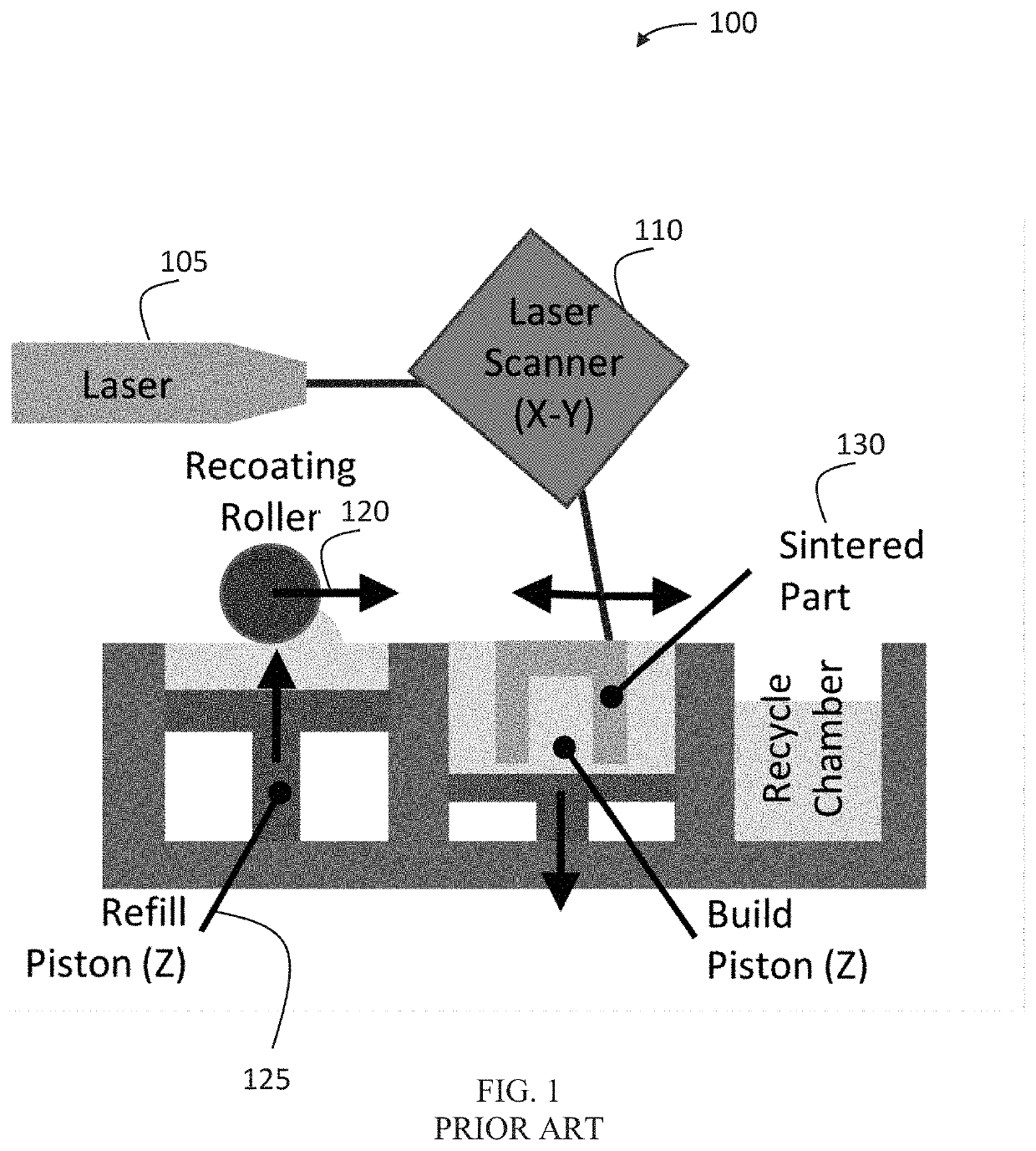
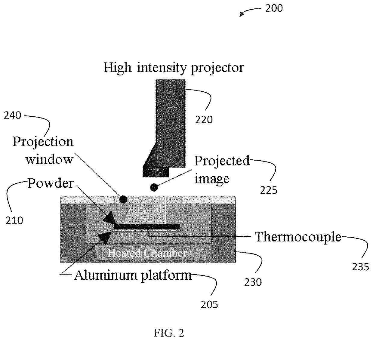
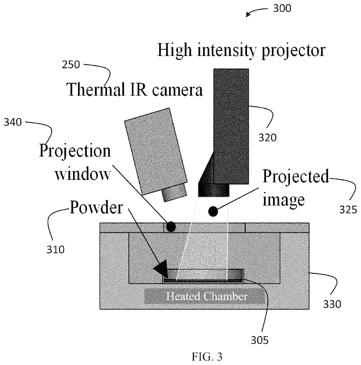
[0018]The layerwise additive manufacturing dynamic mask methodologies of the present invention are capable of fusing an entire layer of heated powder at one time inside a thermally controlled chamber.

[0019]As shown in FIG. 1, a typical industrial SLS system 100 includes a high power laser 105, a galvanometer 110 for steering the laser 105 and a powder spreading system 120, 125 contained within a closed inert environment. During the SLS process, the laser 105 and laser scanner 110 sinters the powder in the X-Y axis while the recoating roller 120 and refill piston 125 supplies powder to a new layer. Industrial SLS systems 100 are relatively expensive and complex, thereby rendering the system out of range for most users. In order to produce parts 130 economically and with high spatial resolution, commercial SLS systems generally incorporate a small diameter laser (˜0.5 mm) with a high scanning speed (˜1-5 m / s) to accomplish the sintering of the powdered material.

[0020]In traditional se...


PUM

PropertyMeasurementUnit
Areaaaaaaaaaaa
Temperatureaaaaaaaaaa
Surface areaaaaaaaaaaa

Abstract

A material processing and associated additive manufacturing system and method that utilizes high intensity light to fuse an entire layer of material, at one time, to create a three-dimensional component. The system and method of the present invention allows for each layer to be created in a fraction of the time, thereby reducing the overall time for a three-dimensional component to be created, thereby increasing control over the properties achieved.

Description

CROSS-REFERENCE TO RELATED APPLICATIONS[0001]This invention claims priority to U.S. Provisional Patent Application No. 62 / 202,540 filed Aug. 7, 2015 entitled “Layerwise Additive Manufacturing Utilizing Dynamic Masks Technology”, the content of which is incorporated herein by reference.BACKGROUND OF THE INVENTION[0002]Additive manufacturing (AM) is an industrial manufacturing method used to create three-dimensional components from solid digital computer models. Typically, the three-dimensional components are sliced into two-dimensional cross sections of a prescribed thickness and each two-dimensional cross section is then reproduced from the feedstock material. These two-dimensional cross sections are stacked on top of each other and fused to the layer beneath, thereby reproducing components with complex three-dimensional geometry. The layering nature of AM allows each part to be unique without requiring custom tooling, but frequently at the cost of fabrication time.[0003]Additive ma...

Claims


Application Information

Patent Timeline
IPC IPC(8): B23K26/12B29C67/00B33Y30/00B33Y40/00B33Y10/00B33Y70/00
CPCB33Y30/00B33Y70/00B33Y40/00B33Y10/00B29C67/0092B29C67/0077B33Y50/02B29C64/153B29C64/393B29C64/277B29C64/295Y02P10/25B29C64/40B29C64/268
Inventor CRANE, NATHAN BRADNUSSBAUM, JUSTIN TROY
Owner UNIV OF SOUTH FLORIDA
Why Eureka
Try Eureka