Internal combustion engine
a combustion engine and combustion chamber technology, applied in the direction of valve arrangements, machines/engines, mechanical equipment, etc., can solve the problems of increasing the amount of heat transfer, and achieve the effect of reducing the amount of heat that passes between the valve and the gas, reducing the surface area of the valve, and reducing the roughness of the valve surfa
- Summary
- Abstract
- Description
- Claims
- Application Information
AI Technical Summary
Benefits of technology
Problems solved by technology
Method used
Image
Examples
first embodiment
1. First Embodiment
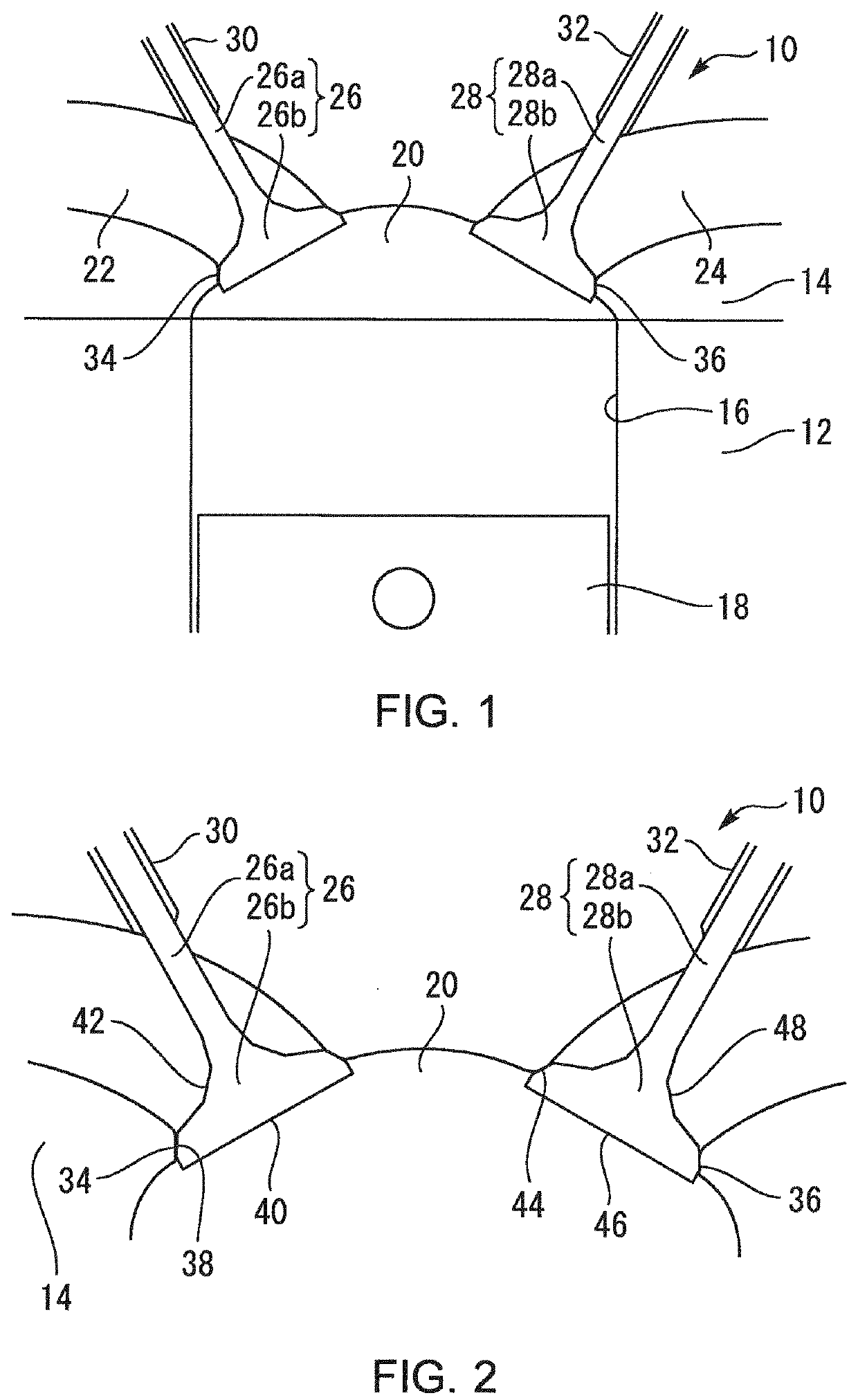
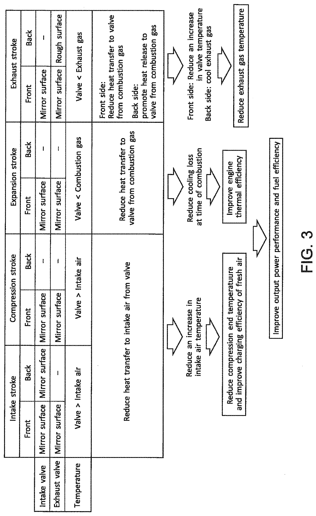
[0040]A first embodiment according to the present disclosure will be described with reference to FIGS. 1 to 3.
1-1. Example of Configuration of Internal Combustion Engine
[0041]FIG. 1 is a schematic diagram for describing an example of the configuration of an internal combustion engine 10 according to the first embodiment of the present disclosure. As shown in FIG. 1, the internal combustion engine 10 is equipped with a cylinder block 12, and a cylinder head 14 fastened to an upper part of the cylinder block 12. Cylinder bores 16 are formed in the interior of the cylinder block 12. In each of these cylinder bores 16, a piston 18 that reciprocates in the axial direction of the relevant cylinder bore 16 is arranged. In each cylinder of the internal combustion engine 10, a combustion chamber 20 is defined by a wall surface of the relevant cylinder bore 16, an undersurface of the cylinder head 14, and a top surface of the piston 18.
[0042]In the cylinder head 14, an inta...
second embodiment
2. Second Embodiment
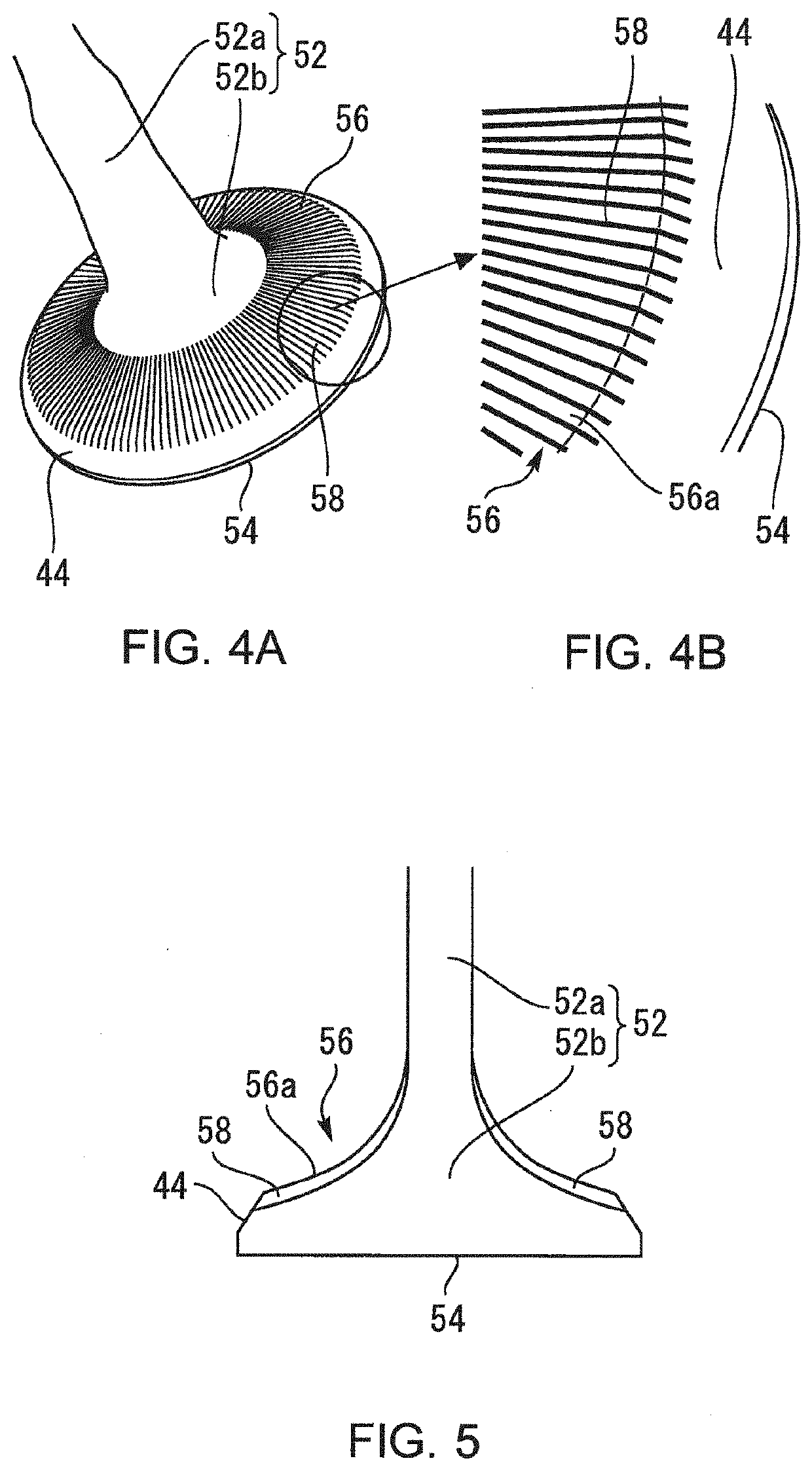
[0067]Then, a second embodiment according to the present disclosure will be described with reference to FIGS. 4 to 6.
2-1. Configuration of Exhaust-Valve-Head Back Surface
[0068]FIG. 4A is a whole perspective view that illustrates a main part of an exhaust valve 52 according to the second embodiment of the present disclosure; and FIG. 4B is an enlarged view of a part of radial grooves 58 shown in FIG. 4A. An internal combustion engine 50 (see FIG. 6 described below) according to the second embodiment is different from the internal combustion engine 10 according to the first embodiment in terms of including the exhaust valve 52 shown in FIG. 4A, instead of the exhaust valve 28 shown in FIG. 1.
[0069]As shown in FIG. 4A, the exhaust valve 52 is provided with an exhaust valve shaft 52a and an exhaust valve head 52b formed into an umbrella shape. Similarly to the exhaust valve 28 shown in FIG. 1, the surface of the exhaust valve 52 includes an exhaust-valve-head front s...
third embodiment
3. Third Embodiment
[0085]Then, a third embodiment according to the present disclosure will be described with reference to FIGS. 7 and 8.
[0086]In the internal combustion engine 10 according to the first embodiment described above, each of the intake-valve-head front surface 40, the intake-valve-head back surface 42, the exhaust-valve-head front surface 46 and the exhaust-valve-head back surface 48 is finished such that the roughness becomes even on the whole, as already described. In contrast to this, an intake valve 70 and an exhaust valve 80 according to the third embodiment are different from the intake valve 26 and the exhaust valve 28, respectively, in the points described below with reference to FIGS. 7 and 8.
3-1. Setting of Roughness of Each Surface of Intake Valve
[0087]FIG. 7 is a diagram for describing an example of the setting of the surface roughness of individual portions of the intake valve 70 according to the third embodiment of the present disclosure. According to the ...
PUM
 Abstract
Description
Claims
Application Information
 - R&D
- Intellectual Property
- Life Sciences
- Materials
- Tech Scout
- Unparalleled Data Quality
- Higher Quality Content
- 60% Fewer Hallucinations
Browse by: Latest US Patents, China's latest patents, Technical Efficacy Thesaurus, Application Domain, Technology Topic, Popular Technical Reports.
© 2025 PatSnap. All rights reserved.Legal|Privacy policy|Modern Slavery Act Transparency Statement|Sitemap|About US| Contact US: help@patsnap.com


