
Electrically heatable honeycomb body for exhaust gas treatment having a plurality of heating elements

a technology of heating elements and honeycombs, which is applied in the direction of heater elements, machines/engines, separation processes, etc., can solve the problems of limited conventional methods of ep 0 603 222 b1, which are limited by increasing the thickness of heating elements, and achieve improved heat exchange, improved heat conduction, and high stability

Active Publication Date: 2021-01-19
VITESCO TECH GERMANY GMBH
View PDF27 Cites 0 Cited by
  • Summary
  • Abstract
  • Description
  • Claims
  • Application Information

AI Technical Summary

Benefits of technology

The present invention provides a honeycomb body structure that can be heated electrically using voltages of +24 to -48 V and collective power of 500 to 50000 W. The heating elements are designed to operate at +24 to -48 V and can collectively receive power of +1000 to -3000 W. The design parameters allow for the distribution of heating power within the interior of the honeycomb body to be selected widely. The pressure loss is kept low by the electric heating for gas flowing through the honeycomb body. Openings and flow-guiding elements in the sheet metal layers can divert gas even into regions of the honeycomb body that are blocked by the heating elements. The honeycomb body can be heated inhomogeneously in the flow direction with at least three heating elements that have different spacings. The sheet metal layers can also be joined by joining techniques to achieve higher stability and better heat conduction.

Problems solved by technology

It can be seen, however, that this conventional method of EP 0 603 222 B1 is limited with increasing thickness of the heating element.

Method used


Image

  • Electrically heatable honeycomb body for exhaust gas treatment having a plurality of heating elements
  • Electrically heatable honeycomb body for exhaust gas treatment having a plurality of heating elements
  • Electrically heatable honeycomb body for exhaust gas treatment having a plurality of heating elements

Examples


Embodiment Construction

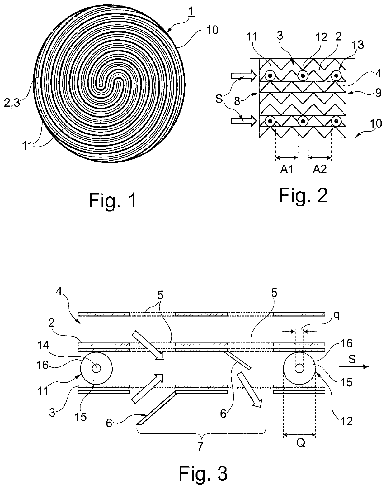
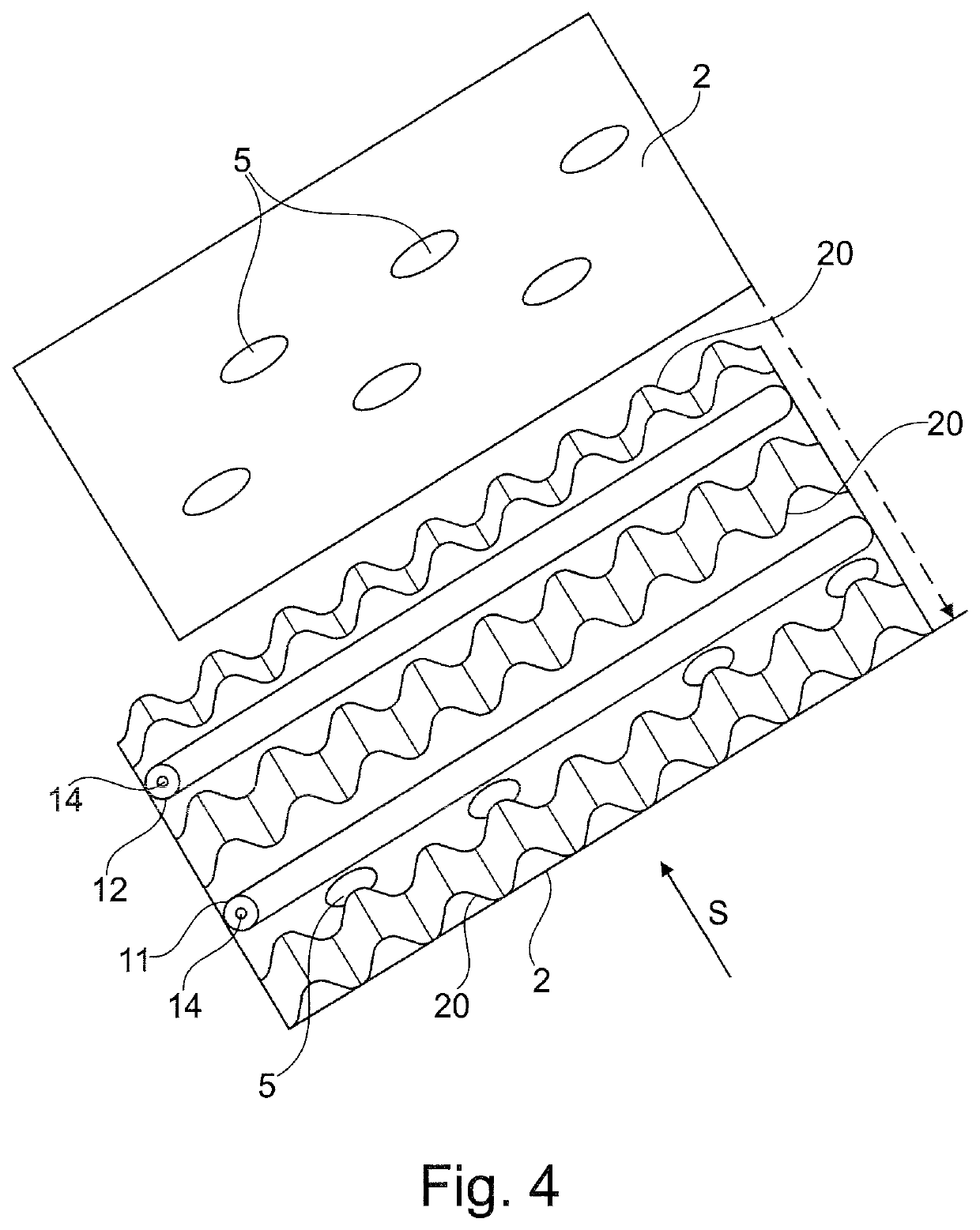
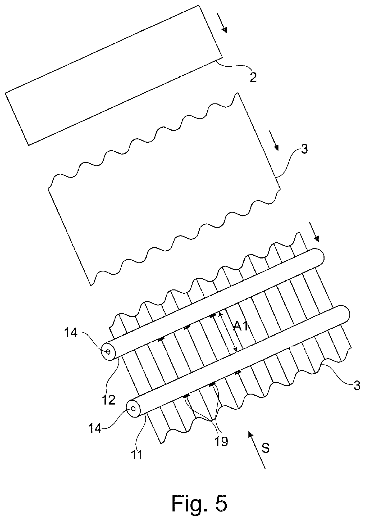
[0031]FIG. 1 schematically shows a cross section through an electrically heatable honeycomb body 1 according to an aspect of the invention, which is constructed from smooth 2 and corrugated 3 sheet metal layers. The present exemplary embodiment involves a honeycomb body constructed from an intertwined sheet metal stack with two heating elements 11, which means that also two heating elements 11 are used for heating a cross-sectional region. The entire honeycomb body is surrounded by a jacket tube, through which the heating elements 11 are guided in a manner known per se to the outside to an electrical connection (not illustrated).

[0032]FIG. 2 shows a schematic longitudinal section through a honeycomb body 1 according to an aspect of the invention, wherein corrugated sheet metal layers 3 are illustrated by zigzag lines, although the corrugation actually runs rotationally offset by 90° with respect to the zigzag lines shown. The honeycomb body 1 is composed of alternately arranged smoo...


PUM


Abstract

A honeycomb body includes: a first end face; a second end face, the honeycomb body being configured to permit gas flow through the honeycomb body from the first end face to the second end face in a flow direction; and a plurality of at least partially structured sheet metal layers, layered one on top of the other and entwined with each other to form gas-permeable channels. At least one of the plurality of sheet metal layers is reinforced or replaced by at least two elongate electrical heating elements arranged approximately parallel to one another with a spacing one behind the other in the flow direction and extending transversely to the flow direction.

Description

CROSS-REFERENCE TO RELATED APPLICATIONS[0001]This is a U.S. national stage of international application No. PCT / EP2017 / 068066 filed on 18 Jul. 2017, which claims priority to the German Application No. 10 2016 214 495.2 filed 4 Aug. 2016, the content of both incorporated herein by reference.BACKGROUND OF THE INVENTION1. Field of the Invention[0002]The present invention relates to the field of electrically heatable honeycomb bodies, in particular for use in the exhaust gas purification of internal combustion engines, preferably in motor vehicles.2. Related Art[0003]Electrically heatable honeycomb bodies are mainly used in motor vehicles as catalytic converter substrate bodies through which exhaust gas can flow and which, under certain operating conditions, for example during a cold start, are electrically heated to quickly reach a suitable temperature for catalytic reactions, or to maintain this even under unfavorable conditions.[0004]Electrically heatable honeycomb bodies and their c...

Claims


Application Information

Patent Timeline
Patent Type & Authority Patents(United States)
IPC IPC(8): F01N3/20F01N3/28F01N3/027B01D53/94H05B3/06
CPCF01N3/2013B01D53/94F01N3/027F01N3/281H05B3/06F01N2240/16F01N2330/02F01N2330/38F01N2590/08H05B2203/005H05B2203/016Y02A50/20Y02T10/12
Inventor HIRTH, PETERPABST, CHRISTOPH
Owner VITESCO TECH GERMANY GMBH
Learn More