Inductor/transformer with closed ring

a transformer and closed-ring technology, applied in the direction of transformer/inductance details, basic electric elements, inductances, etc., can solve the problem that the desired bandwidth cannot be achieved for a component, and achieve the effect of wide bandwidth signal, lower resistance of the inductor, and higher quality (q) factor of the inductor

Active Publication Date: 2021-01-19
QUALCOMM INC
View PDF1 Cites 0 Cited by
  • Summary
  • Abstract
  • Description
  • Claims
  • Application Information

AI Technical Summary

Benefits of technology

[0004]The described aspects generally relate to adjust the quality (Q) factor of an inductor formed on a chip. In some applications, such as power amplified RF signal, there can be large bias currents passed through the inductor. Using large bias currents require the use of large (thick / wide) conductive traces to form the inductor to prevent electromigration (EM). Making the conductor used to form the inductor large (thick / wide) can minimize EM but it also lowers the resistance of the inductor leading to a higher quality (Q) factor of the inductor. In some applications it is desirable to have a inductor with a lower Q so that a wider bandwidth signal can be passed through the inductor.

Problems solved by technology

However, some design requirements may be such that a desired bandwidth cannot be achieved for a component.

Method used


Image

  • Inductor/transformer with closed ring
  • Inductor/transformer with closed ring
  • Inductor/transformer with closed ring

Examples


Embodiment Construction

[0018]Aspects disclosed in the following description and related drawings are directed to specific embodiments. Alternative embodiments may be devised without departing from the scope of the invention. Additionally, well-known elements may not be described in detail, or may be omitted, so as not to obscure relevant details. Embodiments disclosed may be suitably included in any electronic device.

[0019]With reference now to the drawing, several exemplary aspects of the present disclosure are described. The word “exemplary” is used herein to mean “serving as an example, instance, or illustration.” Any aspect described herein as “exemplary” is not necessarily to be construed as preferred or advantageous over other aspects. Furthermore, the terminology used herein is for the purpose of describing particular embodiments and is not intended to be limiting

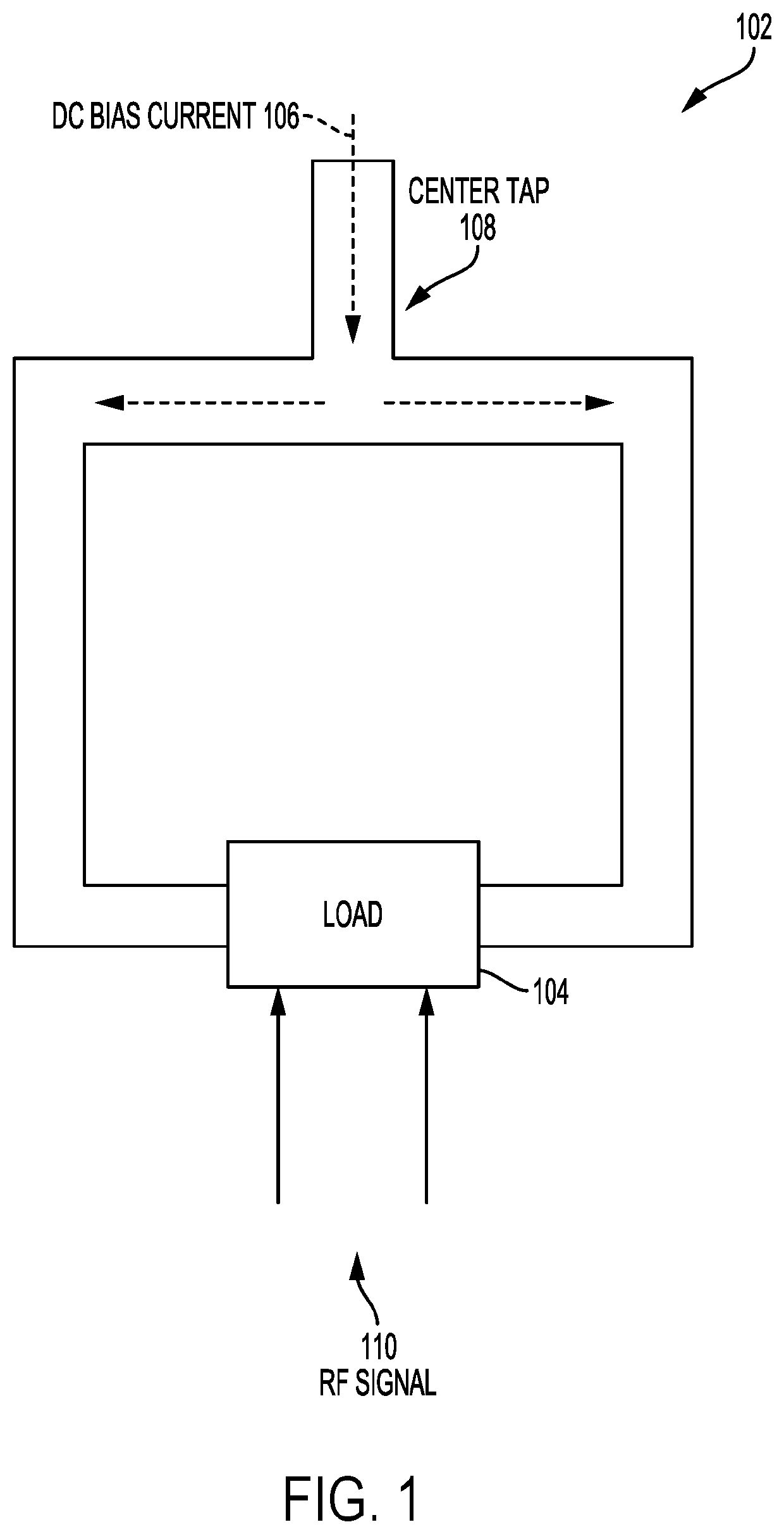
[0020]FIG. 1 is a drawing of an inductor 102. In the example of FIG. 1, the inductor 102 is a single loop, in other embodiments the induc...


PUM

PropertyMeasurementUnit
conductiveaaaaaaaaaa
band widthaaaaaaaaaa
bias currentsaaaaaaaaaa

Abstract

Aspects generally relate to adjusting, or lowering, the Q of an inductor. In one embodiment, an integrated circuit includes an inductor and a conductive closed ring inside a periphery of the inductor. In another embodiment, there can be a plurality of closed rings inside the periphery of the inductor. The conductive closed rings are magnetically coupled to the inductor to adjust the Q.

Description

BACKGROUNDI. Field of the Disclosure[0001]Aspects of the disclosure relate generally to inductors and transformers, and in particular to adjusting the quality (Q) factor of the inductor or transformer.II. Background[0002]As wireless communication systems continue to evolve there is increasing need to improve performance of radio frequency (RF) devices. Some types of RF device applications there is a need to pass narrow bandwidth signals, while in other applications it may be desirable to pass wide bandwidth signals. For example, in the fifth generation (5G) standard being developed there may be a need to pass wide bandwidth signals for components such as amplifiers. To meet these requirements the components used in circuitry need to be able to pass wide bandwidth signals. However, some design requirements may be such that a desired bandwidth cannot be achieved for a component.[0003]There is a need for mechanisms and methods to produce components that will pass the desired band width...

Claims


Application Information

Patent Timeline
Patent Type & Authority Patents(United States)
IPC IPC(8): H01L49/02H01F17/00H01L23/522H01L27/08
CPCH01L28/10H01F17/0006H01L23/5227H01L27/08H01F2017/0046H03J2200/35H01F27/2804H01F27/38H01F2017/0053H01F2017/0073H01F2027/348
Inventor CHENG, HAITAOSONG, CHAOLU, YE
Owner QUALCOMM INC
Why Eureka
Try Eureka