Distance measuring device, imaging apparatus, moving device, robot device, and recording medium

a technology of distance measurement and moving device, which is applied in the direction of manufacturing tools, using reradiation, instruments, etc., can solve the problems of reducing the reproducibility of distance information, varying distance information, and error in distance information acquired by imaging plane phase difference distance measurement method, so as to achieve high color reproducibility and reduce the effect of distance information error

Active Publication Date: 2021-01-26
CANON KK
View PDF4 Cites 0 Cited by
  • Summary
  • Abstract
  • Description
  • Claims
  • Application Information

AI Technical Summary

Benefits of technology

[0007]According to the present invention, an image having high color reproducibility is obtained by a distance measuring device and error in the distance information is reduced.

Problems solved by technology

One factor in an error of the distance information acquired by the imaging plane phase difference distance measuring method is due to a noise included in the image used for calculating a parallax amount.
Even in objects having the same distance, the distance information varies due to a noise depending on the timing for acquiring the distance information.
If an amount of received light of a photoelectric conversion unit that configures each pixel portion of the imaging element is small, the influence of noise increases, and consequently, the reproducibility of the distance information may decrease.
Additionally, another factor related to an error of the distance information is chromatic aberration of the imaging optical system provided in the imaging apparatus.
Since the imaging optical system forms an optical image of the object on the imaging element, an error due to axial chromatic aberration of the imaging optical system affects the distance information.
If the wavelength band pertaining to each pixel portion of the imaging element is wide, an error may occur in the distance information due to the chromatic aberration of the imaging optical system.
If the color reproducibility is low, there is a concern about the erroneous recognition of the surrounding environment and the reduction in the visibility of images.

Method used


Image

  • Distance measuring device, imaging apparatus, moving device, robot device, and recording medium
  • Distance measuring device, imaging apparatus, moving device, robot device, and recording medium
  • Distance measuring device, imaging apparatus, moving device, robot device, and recording medium

Examples


first embodiment

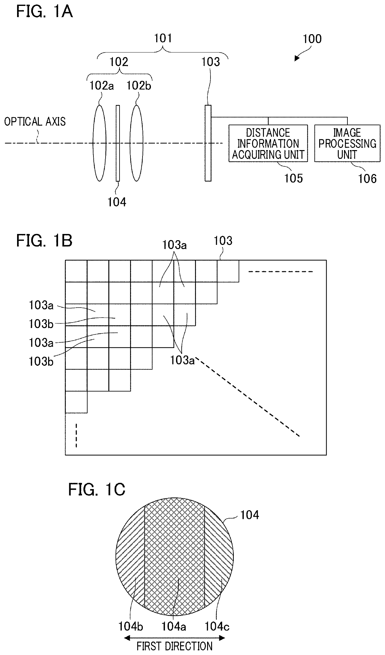
[0026]FIGS. 1A and 1B schematically illustrate a configuration of a distance measuring device according to a first embodiment of the present invention. FIG. 1A is a schematic diagram illustrating an imaging unit 101, a distance information acquiring unit 105, and an image processing unit 106, which are main components of a distance measuring device 100. The imaging unit 101 includes an imaging optical system 102 and an imaging element 103 in which many pixel portions are arranged. The imaging optical system 102 includes a plurality of lenses. For example, reflected light from an object forms an image on the imaging element 103 by lenses 102a and 102b arranged along the optical axis. The imaging optical system 102 includes an optical filter 104 at a diaphragm position between the lenses 102a and 102b.

[0027]FIG. 1B is a schematic diagram illustrating the pixel arrangement of the imaging element 103. Many pixel portions of the imaging element 103 are configured by a first pixel portio...

modification 1

of the First Embodiment

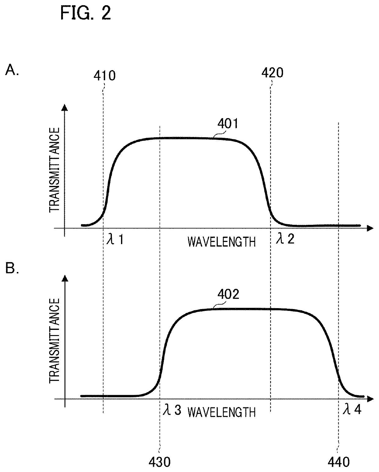
[0059]Modification 1 according to the first embodiment will be described with reference to FIGS. 8A to 8D. In the present modification, the configuration of the imaging pixel portion 103a and the distance measuring pixel portion 103b of the imaging element 103 are different from the above-described configuration. In the optical filter 104 according to the present modification, the second region 104b and the third region 104c have the spectral transmittance characteristics shown in B of FIG. 7. In the following description, the same reference numerals or symbols as those in the first embodiment are used, the detailed description thereof will be omitted, and mainly the differences will be explained. Such omission of explanation is also the same in modifications, embodiments, and the like which will be described below.

[0060]FIG. 8A illustrates the light receiving plane of an imaging pixel portion 803a included in the imaging element 103 according to the present m...

modification 2

of the First Embodiment

[0068]With reference to FIGS. 11A and 11B, a description will be given of a method for setting different wavelength bands between the imaging light flux and the distance measuring light flux in the modification 2 of the first embodiment. The imaging optical system according to the present modification has a configuration in which the optical filter 104 is removed from the imaging optical system 102.

[0069]FIG. 11A is a schematic diagram that illustrates the imaging pixel portion according to the modification and is a diagram in which an imaging pixel portion 1301a is viewed from the side. The imaging pixel portion 1301a includes the micro lens 221 and the photoelectric conversion portion 211. The imaging pixel portion 1301a includes an imaging color filter 1320a, and spectral sensitivities of blue, green, and red are applied in accordance with the spectral transmittance.

[0070]FIG. 11B is a schematic diagram that illustrates a distance measuring pixel portion ac...


PUM


Abstract

A distance measuring device includes an imaging optical system having an optical filter and an imaging element in which a plurality of pixel portions is arranged. The optical filter is divided into three regions, the first region has a first spectral transmittance characteristic, and the second region and the third region a second spectral transmittance characteristic in which light having a longer wavelength compared to the first spectral transmittance characteristic is transmitted. The first pixel portion that configures the imaging element includes a first photoelectric conversion unit and receives light that has passing through the first region. The second pixel portion that configures the imaging element includes second and third photoelectric conversion units, and receives light that has passed through each of the second region and the third region. A distance information acquiring unit acquires distance information corresponding to parallax of image data based on each of the output signals from the second and third photoelectric conversion units.

Description

BACKGROUND OF THE INVENTIONField of the Invention[0001]The present invention relates to a distance measuring technique using an imaging plane phase difference method.Description of the Related Art[0002]A distance measuring device is mounted on a moving member, for example, a vehicle, a drone, or a robot, and measures a distance between the moving member and its surroundings or obstacles in order to support action. In particular, in order to avoid collision with obstacles or to support action directed at the tracking of a specified object, a recognition process using an image is required, and an imaging apparatus is used for performing distance measurement.[0003]Japanese Patent No. 5917207 discloses an imaging apparatus using an imaging plane phase difference method, which can acquire not only an image to be used for the recognition process but also a distance. In the imaging plane phase difference distance measuring method, two image data based on an optical image generated by a lig...

Claims


Application Information

Patent Timeline
Patent Type & Authority Patents(United States)
IPC IPC(8): G01B11/02G01S17/08
CPCG01B11/026G01S17/08H01L27/14621H01L27/14645G01S17/89G01S17/931G02B5/201G02B7/34B25J19/021G01B11/2545
Inventor NOBAYASHI, KAZUYA
Owner CANON KK
Why Eureka
Try Eureka